5 WIRING
- 45 -
5.6 Wiring Remote I/O Cables
•
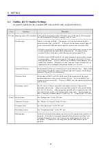
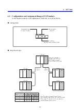
The CPU unit has two remote I/O cable ports (RI/O-1 and RI/O-2), each of which can connect
up to 12 I/O units.
•
The remote I/O cable ports, RI/O-1 and RI/O-2, on the I/O unit are connected internally.
Connect the cable extended from the previous stage to RI/O-1, and connect the cable
extended to the next stage to RI/O-2.
•
Use terminating resistors to terminate the CPU modules or remote I/O station modules
connected to both ends of a remote I/O line. The user can select the built-in 100
Ω
or 150
Ω
resistor or an external resistor having a suitable resistance. Check the characteristic
impedance of the remote I/O cable to select the most suitable terminating resistor. For
details, see “5.6.3 Setting terminating resistors.”
•
If the remote I/O cable is connected improperly, communication may fail. Connect the
remote I/O cable as specified. For details, see “5.6.1 Examples of improper wiring.”
•
After the remote I/O cable is connected, set the CPU module and remote I/O station module,
as described in “6 SETTINGS.”
•
Ground to a single point the shield terminals of all remote I/O cables that are connected with
each communications line. Do not ground the FG terminal for each hardware unit.
CPU unit
I/O unit 3
I/O unit 2
I/O unit 1
I/O unit 1
I/O unit N
I/O unit 2
I/O unit N
RI/O
1 2
N
≤
12
N
≤
12
RI/O-2
RI/O-1
Must be
terminated.
Must be
terminated.
RI/O
1 2
RI/O
1 2
RI/O
1 2
RI/O
1 2
RI/O
1 2
RI/O
1 2
RI/O
1 2
Must be
terminated.
Must be
terminated.
NOTE
Attach a terminator (150
Ω
) to those ports to which the remote I/O cable is not
connected to guard against external electromagnetic noise.
Summary of Contents for S10mini D
Page 1: ......
Page 14: ...THIS PAGE INTENTIONALLY LEFT BLANK ...
Page 19: ...1 BEFORE USE ...
Page 28: ...THIS PAGE INTENTIONALLY LEFT BLANK ...
Page 29: ...2 OVERVIEW ...
Page 34: ...THIS PAGE INTENTIONALLY LEFT BLANK ...
Page 35: ...3 NAMES AND FUNCTIONS OF PARTS ...
Page 45: ...4 INSTALLATION ...
Page 54: ...THIS PAGE INTENTIONALLY LEFT BLANK ...
Page 55: ...5 WIRING ...
Page 68: ...THIS PAGE INTENTIONALLY LEFT BLANK ...
Page 69: ...6 SETTING ...
Page 84: ...THIS PAGE INTENTIONALLY LEFT BLANK ...
Page 85: ...7 OPERATION PROCEDURES ...
Page 91: ...8 EXPLANATION OF OPERATION ...
Page 111: ...9 MAINTENANCE ...
Page 128: ...THIS PAGE INTENTIONALLY LEFT BLANK ...
Page 129: ...10 SPECIFICATIONS ...

