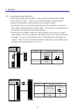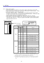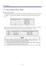
7 OPERATION PROCEDURES
- 70 -
7.2.3 RUN (ladder program execution) mode
Setting
• Set the CPU operation switch (LADDER)
to RUN.
• Set the mode switch (MODE) to NORM.
CPU status
The user program (ladder) is executed.
7.2.4 SIMU (simulated ladder program execution) mode
Setting
Set the CPU operation switch (LADDER) to
RUN, and also set the mode switch (MODE)
to SIMU.
CPU status
• The user program (ladder) is debugged
with the I/O section stopped.
• User tasks continue their execution.
• Remote I/O transfer stops.
7.2.5 RESET mode
Setting
Hold down the RESET switch for one
second.
Note: Do not press the RESET switch hard.
CPU status
During resetting:
• The indicator displays nothing.
• The program and remote I/O transfer stop.
After resetting:
• The I/O registers (X and Y) and internal
registers (identified by other letters) are
cleared. However, the keep relay (K),
counter (C), or fixed-constant (D) register
is not cleared.
• The CPU starts according to the settings of
the LADDER, MODE, and PROTECT
switches on the CPU module.
HITACHI
S10mini
LQP000
LADDER
MODE
PROTECT
RESET
STOP
RUN
SIMU
NORM
OFF
ON
CPU RUN
HITACHI
S10mini
LQP000
LADDER
MODE
PROTECT
RESET
STOP
RUN
SIMU
NORM
OFF
ON
CPU SIMU
HITACHI
S10mini
LQP000
LADDER
MODE
PROTECT
RESET
STOP
RUN
SIMU
NORM
OFF
ON
Press
Summary of Contents for S10mini D
Page 1: ......
Page 14: ...THIS PAGE INTENTIONALLY LEFT BLANK ...
Page 19: ...1 BEFORE USE ...
Page 28: ...THIS PAGE INTENTIONALLY LEFT BLANK ...
Page 29: ...2 OVERVIEW ...
Page 34: ...THIS PAGE INTENTIONALLY LEFT BLANK ...
Page 35: ...3 NAMES AND FUNCTIONS OF PARTS ...
Page 45: ...4 INSTALLATION ...
Page 54: ...THIS PAGE INTENTIONALLY LEFT BLANK ...
Page 55: ...5 WIRING ...
Page 68: ...THIS PAGE INTENTIONALLY LEFT BLANK ...
Page 69: ...6 SETTING ...
Page 84: ...THIS PAGE INTENTIONALLY LEFT BLANK ...
Page 85: ...7 OPERATION PROCEDURES ...
Page 91: ...8 EXPLANATION OF OPERATION ...
Page 111: ...9 MAINTENANCE ...
Page 128: ...THIS PAGE INTENTIONALLY LEFT BLANK ...
Page 129: ...10 SPECIFICATIONS ...

