1 BEFORE USE
- 8 -
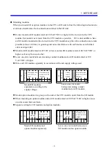
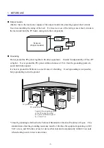
Grounding
* Check the wiring made for grounding.
•
Is the ground line shared with other units?
•
Is the grounding point of the S10mini controller separated from that of a power distribution
panel by at least 15 m?
* Make sure that signal cables such as remote I/O cables are well apart from the power cables.
S10mini
Separated ground line
Another unit
S10mini
Another unit
Shared ground line
DANGER
Form emergency shutdown circuits, interlock circuits or the like outside the
programmable controller. Failures in the programmable controller may result
in damage to the equipment or accidents.
Use the I/O current with any I/O module within the maximum allowable limit.
Overcurrent flow can cause damage to the parts, resulting in accidents, fires,
or failures.
Choose an external power supply with overvoltage and overcurrent protection
features.
When the programmable controller smokes, gives off an offensive smell, or
otherwise misbehave, turn it off immediately and probe into the cause.
CAUTION
Choose a power supply matching the rating of a module and connect it to that
module. Connecting an improper power supply to a module can cause the
module to fire.
Parts containing gallium arsenide (GaAs) in a PC or LED are used in this
product. Gallium arsenide is designated as a harmful substance by law.
Use maximum discretion in handling and particularly scrapping the product.
Have a specialized agent dispose of the product as industrial waste.
Use the same power supply for the external power supply (fed to the +V
terminal) of the S10mini output module and for the load power supply. Use of
different power supplies can cause malfunctioning.
Do not use transceivers, cell phones or the like near the system.
Electromagnetic noise interference from such gear can cause the system to
malfunction.
Summary of Contents for S10mini D
Page 1: ......
Page 14: ...THIS PAGE INTENTIONALLY LEFT BLANK ...
Page 19: ...1 BEFORE USE ...
Page 28: ...THIS PAGE INTENTIONALLY LEFT BLANK ...
Page 29: ...2 OVERVIEW ...
Page 34: ...THIS PAGE INTENTIONALLY LEFT BLANK ...
Page 35: ...3 NAMES AND FUNCTIONS OF PARTS ...
Page 45: ...4 INSTALLATION ...
Page 54: ...THIS PAGE INTENTIONALLY LEFT BLANK ...
Page 55: ...5 WIRING ...
Page 68: ...THIS PAGE INTENTIONALLY LEFT BLANK ...
Page 69: ...6 SETTING ...
Page 84: ...THIS PAGE INTENTIONALLY LEFT BLANK ...
Page 85: ...7 OPERATION PROCEDURES ...
Page 91: ...8 EXPLANATION OF OPERATION ...
Page 111: ...9 MAINTENANCE ...
Page 128: ...THIS PAGE INTENTIONALLY LEFT BLANK ...
Page 129: ...10 SPECIFICATIONS ...

