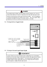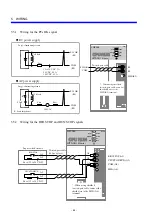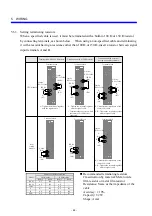
5 WIRING
- 42 -
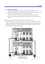
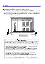
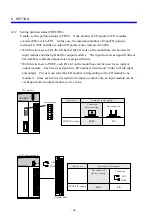
Sample wiring when the I/O unit is installed in a different enclosure
When a remote I/O cable is used to connect enclosures installed in different places, do not ground
the FG terminal on the remote I/O station module positioned between them. If it is grounded,
immunity to noise is lowered due to different ground potentials. Ground the FG terminal on only
one of the units of the two terminating ends.
PS
LQV000
POWER
ON
OFF
H
N
LG
FG
AC100-120V
DC5V
GND
SERVICE
CHECK
POWER
LQS000
HITACHI
HSC-1000
RI/O
D.INPUT
LQX100
100-120VAC
0
1
2
3
4
5
6
7
8
9
A
B
C
D
E
F
D.INPUT
LQX100
100-120VAC
0
1
2
3
4
5
6
7
8
9
A
B
C
D
E
F
LG
FG
FG
PS
RI/O
I/O
I/O
FG
(See wiring for the power supply.)
Do not ground the FG terminal
on the RI/O station module.
Terminal block
(single point for LG)
LG
(See wiring for the power supply.)
FG and LG cable sizes
Inside the enclosure: 2 mm
2
or more
Outside the enclosure: 5.5 mm
2
or more
Terminal block
(single point for FG)
RI/O
U
L
ST.NO
REQUIREMENT
An electric shock may lead to a death or burn. Noise may cause the system to
malfunction. Ground the line ground (LG), frame ground (FG), and shield (SHD)
terminals, as described below.
•
Leave the mount base insulated from the enclosure. To assure this, do not
remove the insulating sheet from the mount base.
•
Ground the LG and FG terminals separately. The LG terminal is provided to
prevent intrusion of power supply noise, while FG and SHD are grounding
terminals that suppress intrusion of line noise into external interfaces for remote
I/O modules, interface modules, or other modules. To prevent mutual
interference, ground the LG and FG terminals separately.
•
Connect the FG terminal on each module to the FG terminal on the mount
base. Have the FG terminal of any external interface line (such as a remote
I/O line or OPCN-1 line) grounded at a single point (terminating side) per line.
Summary of Contents for S10mini D
Page 1: ......
Page 14: ...THIS PAGE INTENTIONALLY LEFT BLANK ...
Page 19: ...1 BEFORE USE ...
Page 28: ...THIS PAGE INTENTIONALLY LEFT BLANK ...
Page 29: ...2 OVERVIEW ...
Page 34: ...THIS PAGE INTENTIONALLY LEFT BLANK ...
Page 35: ...3 NAMES AND FUNCTIONS OF PARTS ...
Page 45: ...4 INSTALLATION ...
Page 54: ...THIS PAGE INTENTIONALLY LEFT BLANK ...
Page 55: ...5 WIRING ...
Page 68: ...THIS PAGE INTENTIONALLY LEFT BLANK ...
Page 69: ...6 SETTING ...
Page 84: ...THIS PAGE INTENTIONALLY LEFT BLANK ...
Page 85: ...7 OPERATION PROCEDURES ...
Page 91: ...8 EXPLANATION OF OPERATION ...
Page 111: ...9 MAINTENANCE ...
Page 128: ...THIS PAGE INTENTIONALLY LEFT BLANK ...
Page 129: ...10 SPECIFICATIONS ...

