5 WIRING
- 48 -
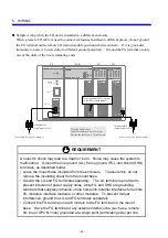
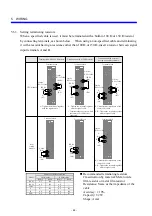
5.6.3 Setting
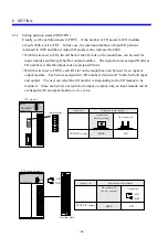
terminating resistors
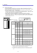
When a specified cable is used, it must be terminated with a built-in 100
Ω
or 150
Ω
resistor
by connecting terminals, as shown below. When using a non-specified cable and terminating
it with a resistor having a resistance other than 100
Ω
or 150
Ω
, insert a resistor between signal
input terminals A and B.
Termination with a 100
Ω
resistor
Termination with a 150
Ω
resistor
Termination with a resistor
having a suitable resistance
CPU module
RI/O
station
module
A
(
A7
)
A
(
A7
)
A
(
B6
)
A
(
B6
)
100
Ω
(
A6
)
100
Ω
(
A9
)
COM
(
A8
)
COM
(
A8
)
150
Ω
(
A7
)
100
Ω
(
B5
)
Terminal block
150
Ω
(
A5
)
150
Ω
(
B4
)
Terminal block
Terminal block
R
R
R
A
(
A7
)
B
(
A8
)
A
(
A4
)
B
(
A5
)
A
(
B6
)
B
(
B7
)
On the
RI/O-1 side
On the
RI/O-1 side
On the
RI/O-1 side
R: Characteristic impedance of the
remote I/O cable
A, B: Tighten the terminal together
with the signal cable.
A: Tighten the terminal together
with the signal cable.
A: Tighten the terminal together
with the signal cable.
* Terminate those ports to which
the remote I/O cable is not
connected.
R: Characteristic impedance of the
remote I/O cable
A, B: Tighten the terminal together
with the signal cable.
On the
RI/O-2 side
On the
RI/O-2 side
On the
RI/O-1 side
On the
RI/O-2 side
Terminal block
Terminal block
Terminal block
Recommended terminating resistors
Classification by material: Metal oxide
film resistor or metal film resistor
Resistance: Same as the impedance of the
cable
Accuracy: ± 10%
Capacity: 1/2 W
Shape: Axial
Number on the terminal block
Signal
CPU module
RI/O module
RI/O1
RI/O2
RI/O1
RI/O2
150
Ω
A5 B4 A7
⎯
100
Ω
A6 B5 A9
⎯
COM
⎯
⎯
A8
⎯
A A7 B6 A4 B5
B A8 B7 A5 B6
SHD A9 B8 A6 B7
Summary of Contents for S10mini D
Page 1: ......
Page 14: ...THIS PAGE INTENTIONALLY LEFT BLANK ...
Page 19: ...1 BEFORE USE ...
Page 28: ...THIS PAGE INTENTIONALLY LEFT BLANK ...
Page 29: ...2 OVERVIEW ...
Page 34: ...THIS PAGE INTENTIONALLY LEFT BLANK ...
Page 35: ...3 NAMES AND FUNCTIONS OF PARTS ...
Page 45: ...4 INSTALLATION ...
Page 54: ...THIS PAGE INTENTIONALLY LEFT BLANK ...
Page 55: ...5 WIRING ...
Page 68: ...THIS PAGE INTENTIONALLY LEFT BLANK ...
Page 69: ...6 SETTING ...
Page 84: ...THIS PAGE INTENTIONALLY LEFT BLANK ...
Page 85: ...7 OPERATION PROCEDURES ...
Page 91: ...8 EXPLANATION OF OPERATION ...
Page 111: ...9 MAINTENANCE ...
Page 128: ...THIS PAGE INTENTIONALLY LEFT BLANK ...
Page 129: ...10 SPECIFICATIONS ...


