8 EXPLANATION OF OPERATION
- 84 -
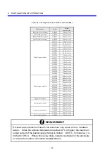
8.6 Restrictions on Mounting Option Modules
Description
Model
CPU unit
I/O unit
Remarks
LQV000
1
1
Shared by CPU and I/O unit
LQV100
1
1
Shared by CPU and I/O unit
LQV020
1
1
Shared by CPU and I/O unit
Power supply
LQV200
1
1
Shared by CPU and I/O unit
CPU (Model S)
LQP000
1
⎯
CPU (Model H)
LQP010
1
⎯
CPU (Model F)
LQP011
1
⎯
CPU (Model D)
LQP120
1
⎯
Extension memory
LQM000
3 (*3)
⎯
Mounted starting with the leftmost position. (*2)
ET.NET
LQE020/LQE520 2
(*9)
⎯
Mounted starting with the leftmost position.
SV.LINK
LQE021/LQE521 2
(*9)
⎯
Mounted starting with the leftmost position.
OD.RING (4 km)
LQE010/LQE510 2
(*1)
⎯
Mounted starting with the leftmost position.
OD.RING (1 km)
LQE015/LQE515 2
(*1)
⎯
Mounted starting with the leftmost position.
SD.LINK LQE030/LQE530
2
(*1)
⎯
Mounted starting with the leftmost position.
FL.NET LQE000/LQE500
2
⎯
Mounted starting with the leftmost position.
CPU link
LQE050/LQE550
2
⎯
Mounted starting with the leftmost position.
RS-232C LQE160/LQE560
2
(*7)
⎯
Mounted starting with the leftmost position.
RS-422 LQE165/LQE565
2
(*7)
⎯
Mounted starting with the leftmost position.
J.NET LQE040/LQE540
2
(*6)
⎯
Mounted starting with the leftmost position.
J.NET-INT LQE045/LQE545
2
(*6)
⎯
Mounted starting with the leftmost position.
IR.LINK LQE046/LQE546
2
(*6)
⎯
Mounted starting with the leftmost position.
D.NET LQE170/LQE570
4
(*8)
⎯
Mounted starting with the leftmost position.
D.NET (power supplied from
on external source)
LQE175/LQE575 4
(*8)
⎯
Mounted starting with the leftmost position.
Standard remote I/O.STATION
LQS000
⎯
1
J.STATION LQS020
⎯
1
LQX100 8 8
LQX200 8 8
LQX201 8 8
LQX300 8 8
(*4)
Digital input
LQX350 8 8
(*4)
LQY100 6 8
LQY140 8 8
LQY200 8 8
LQY300 8 8
(*5)
Digital output
LQY350 8 8
(*5)
Mixed digital I/O
LQZ300
8
8
(*5)
LQA000 8 8
LQA100 8 8
Analog input
LQA200 8 8
LQA500 8 8
Analog output
LQA600 8 8
Pulse counter
LQC000
8
8
Summary of Contents for S10mini D
Page 1: ......
Page 14: ...THIS PAGE INTENTIONALLY LEFT BLANK ...
Page 19: ...1 BEFORE USE ...
Page 28: ...THIS PAGE INTENTIONALLY LEFT BLANK ...
Page 29: ...2 OVERVIEW ...
Page 34: ...THIS PAGE INTENTIONALLY LEFT BLANK ...
Page 35: ...3 NAMES AND FUNCTIONS OF PARTS ...
Page 45: ...4 INSTALLATION ...
Page 54: ...THIS PAGE INTENTIONALLY LEFT BLANK ...
Page 55: ...5 WIRING ...
Page 68: ...THIS PAGE INTENTIONALLY LEFT BLANK ...
Page 69: ...6 SETTING ...
Page 84: ...THIS PAGE INTENTIONALLY LEFT BLANK ...
Page 85: ...7 OPERATION PROCEDURES ...
Page 91: ...8 EXPLANATION OF OPERATION ...
Page 111: ...9 MAINTENANCE ...
Page 128: ...THIS PAGE INTENTIONALLY LEFT BLANK ...
Page 129: ...10 SPECIFICATIONS ...


