8 EXPLANATION OF OPERATION
- 81 -
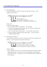
8.4.2 Setting the time using the ladder diagram program
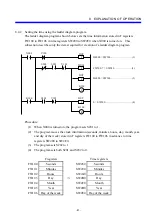
The ladder diagram program shown below sets the time information stored in F registers
FW100 to FW106 in time registers SW280 to SW2E0 when X000 is turned on. This
subsection describes only the items required for creation of a ladder diagram program.
X000
K100
S202
V102
V100
S201
V101
DST
DST
DST
K100
MOM
K100
H4000 = SW200.................................(1)
FW100: 7 = SW280
...........................(2)
H6000 = SW200.................................(3)
0 = SW200..........................................(4)
F
F
F
F
S
R
S200
Procedure:
(1) When X000 is turned on, the program sets S201 to 1.
(2) The program moves the clock information (seconds, minutes, hours, day, month, year,
and day of the week) stored in F registers FW100 to FW106 in advance to time
registers SW280 to SW2E0.
(3) The program sets S202 to 1.
(4) The program sets both S201 and S202 to 0.
F registers
Time registers
FW100 Seconds
SW280
Seconds
FW101 Minutes
SW290
Minutes
FW102 Hours
SW2A0
Hours
FW103 Day
⇒
SW2B0
Day
FW104 Month
SW2C0
Month
FW105 Year
SW2D0
Year
FW106 Day of the week
SW2E0 Day of the week
Summary of Contents for S10mini D
Page 1: ......
Page 14: ...THIS PAGE INTENTIONALLY LEFT BLANK ...
Page 19: ...1 BEFORE USE ...
Page 28: ...THIS PAGE INTENTIONALLY LEFT BLANK ...
Page 29: ...2 OVERVIEW ...
Page 34: ...THIS PAGE INTENTIONALLY LEFT BLANK ...
Page 35: ...3 NAMES AND FUNCTIONS OF PARTS ...
Page 45: ...4 INSTALLATION ...
Page 54: ...THIS PAGE INTENTIONALLY LEFT BLANK ...
Page 55: ...5 WIRING ...
Page 68: ...THIS PAGE INTENTIONALLY LEFT BLANK ...
Page 69: ...6 SETTING ...
Page 84: ...THIS PAGE INTENTIONALLY LEFT BLANK ...
Page 85: ...7 OPERATION PROCEDURES ...
Page 91: ...8 EXPLANATION OF OPERATION ...
Page 111: ...9 MAINTENANCE ...
Page 128: ...THIS PAGE INTENTIONALLY LEFT BLANK ...
Page 129: ...10 SPECIFICATIONS ...


