REQUIREMENT
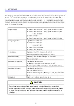
Excessive accumulation of heat in the enclosure may cause a fire or hardware
failure. When the ambient temperature reaches 48°C or higher, the
maximum output current of the power supply module is limited. At 55°C, for
instance, it is limited to 5.85 A. Where this is very likely, install a cooling fan
in the enclosure or reduce the number of modules installed therein.
See Chapter 8 on page 88.
If the battery is handled improperly, it may catch fire or explode. Some used
batteries may still have a considerable amount of charge. To deliver such
used batteries to a waste disposal site safely, follow the general rules for
collection, packing, and transportation. For concrete methods of packing and
transportation, consult with professionals of your local waste disposal
business.
See Chapter 9 on page 100.
REQUIREMENT
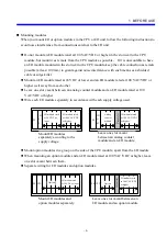
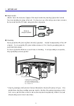
An electric shock may lead to a death or burn. Noise may cause the system to
malfunction. Ground the line ground (LG), frame ground (FG), and shield (SHD)
terminals, as described below.
•
Leave the mount base insulated from the enclosure. To assure this, do not
remove the insulating sheet from the mount base.
•
Ground the LG and FG terminals separately. The LG terminal is provided to
prevent intrusion of power supply noise, while FG and SHD are grounding
terminals that suppress intrusion of line noise into external interfaces for remote
I/O modules, interface modules, or other modules. To prevent mutual
interference, ground the LG and FG terminals separately.
•
Connect the FG terminal on each module to the FG terminal on the mount
base. Have the FG terminal of any external interface line (such as a remote
I/O line or OPCN-1 line) grounded at a single point (terminating side) per line.
See Chapter 5 on page 42.
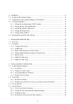
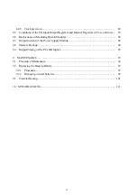
Summary of Contents for S10mini D
Page 1: ......
Page 14: ...THIS PAGE INTENTIONALLY LEFT BLANK ...
Page 19: ...1 BEFORE USE ...
Page 28: ...THIS PAGE INTENTIONALLY LEFT BLANK ...
Page 29: ...2 OVERVIEW ...
Page 34: ...THIS PAGE INTENTIONALLY LEFT BLANK ...
Page 35: ...3 NAMES AND FUNCTIONS OF PARTS ...
Page 45: ...4 INSTALLATION ...
Page 54: ...THIS PAGE INTENTIONALLY LEFT BLANK ...
Page 55: ...5 WIRING ...
Page 68: ...THIS PAGE INTENTIONALLY LEFT BLANK ...
Page 69: ...6 SETTING ...
Page 84: ...THIS PAGE INTENTIONALLY LEFT BLANK ...
Page 85: ...7 OPERATION PROCEDURES ...
Page 91: ...8 EXPLANATION OF OPERATION ...
Page 111: ...9 MAINTENANCE ...
Page 128: ...THIS PAGE INTENTIONALLY LEFT BLANK ...
Page 129: ...10 SPECIFICATIONS ...


