


7 OPERATION PROCEDURES
- 69 -
7.2 Procedures
7.2.1 Turning on the power
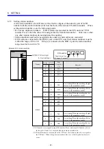
(1) Set the LADDER, MODE, and PROTECT switches on the front of the CPU module to
determine the CPU operation to be performed immediately after the power is turned on.
Operation of the user program (ladder)
Settings of the switches on the CPU module
Display in the indicator
immediately after power-up
LADDER
MODE
PROTECT
immediately after power-up
Preparation for loading
STOP
NORM/SIMU
OFF
CPU STOP
Stop (STOP)
STOP
NORM/SIMU
(*)
CPU STOP
Execution (RUN)
RUN
NORM
(*)
CPU RUN
Simulated execution (SIMU)
RUN
SIMU
(*)
CPU SIMU
(*) Set the switch to ON, if necessary.
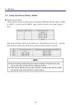
(2) Turn on the power switch on the power module. When the CPU starts up normally, the
following indications are provided:
The operation LED on the power module lights.
The indicator on the CPU module displays the operation status of the CPU.
HITACHI
S10mini
LQP000
LADDER
MODE
PROTECT
RESET
STOP
RUN
SIMU
NORM
OFF
ON
CPU operation switch
(LADDER)
Mode switch
(MODE)
Protection switch
(PROTECT)
CPU STOP
Note: Immediately after power-up, the indicator may display unpredictable character string
instantaneously. This is not a failure.
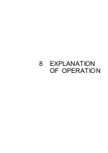
7.2.2 STOP
mode
Setting
Set the CPU operation switch (LADDER) to
STOP.
CPU status
• The user program (ladder) stops.
• The I/O section holds the operation status
immediately before the CPU stops.
• User tasks continue their execution.
• Remote I/O transfer continues.
HITACHI
S10mini
LQP000
LADDER
MODE
PROTECT
RESET
STOP
RUN
SIMU
NORM
OFF
ON
CPU STOP
Summary of Contents for S10mini D
Page 1: ......
Page 14: ...THIS PAGE INTENTIONALLY LEFT BLANK ...
Page 19: ...1 BEFORE USE ...
Page 28: ...THIS PAGE INTENTIONALLY LEFT BLANK ...
Page 29: ...2 OVERVIEW ...
Page 34: ...THIS PAGE INTENTIONALLY LEFT BLANK ...
Page 35: ...3 NAMES AND FUNCTIONS OF PARTS ...
Page 45: ...4 INSTALLATION ...
Page 54: ...THIS PAGE INTENTIONALLY LEFT BLANK ...
Page 55: ...5 WIRING ...
Page 68: ...THIS PAGE INTENTIONALLY LEFT BLANK ...
Page 69: ...6 SETTING ...
Page 84: ...THIS PAGE INTENTIONALLY LEFT BLANK ...
Page 85: ...7 OPERATION PROCEDURES ...
Page 91: ...8 EXPLANATION OF OPERATION ...
Page 111: ...9 MAINTENANCE ...
Page 128: ...THIS PAGE INTENTIONALLY LEFT BLANK ...
Page 129: ...10 SPECIFICATIONS ...