6 SETTING
- 62 -
6.3.5 Setting station numbers
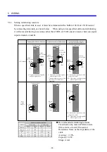
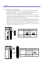
As the station number of an I/O unit, set the first two digits of the numeric part of its I/O
number with the station number switch on the front of the remote I/O station module. When
setting station numbers, note the following points:
• Do not use duplicate numbers. If I/O modules are mounted in the CPU unit and “PI/O
mounted” is set, then the value 00 is assigned as the first station number. Take care so that
any other station numbers do not duplicate this number.
• Station numbers need not be assigned in the order in which cables are connected.
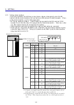
• If I/O units are connected to the RI/O-1 port on the CPU unit, their station numbers must be
within the range of 00 to 3E. If they are connected to the RI/O-2 port, the station number
range must be from 40 to 7E.
LQS000
HITACHI
HSC-1000
RI/O
U
ST.NO
RI/O
Remote I/O station module
U
0
0
0
L
0
1
2
000
010
020
RI/O1
RI/O2
(
*2
)
U L
ST.NO U: First digit
L: Second digit
I/O number
Channel
Setting of ST.NO
First
I/O number
(*1)
Remarks
Last starting I/O number making all eight
slots of 8-slot mount base usable
Last starting I/O number making all four
slots of 4-slot mount base usable
Last starting I/O number making the two
slots of 2-slot mount base usable
400
410
420
380
3C0
3E0
0
1
2
4
4
4
8
C
E
3
3
3
Last starting I/O number making all eight
slots of 8-slot mount base usable
Last starting I/O number making all four
slots of 4-slot mount base usable
Last starting I/O number making the two
slots of 2-slot mount base usable
7C0
7E0
780
8
C
E
7
7
7
L
Input/output type
(X: input, Y: output)
(*1) I/O number is assingned an input I/O number (Xxxx) and output I/O number (Yxxx).
In this table, X and Y are omitted and only numbers are indicated.
(*2) When I/O modules are mounted in the CPU unit, the station number 00 is assigned to
the CPU unit. When setting station numbers, take care so that duplication does not
occur.
Summary of Contents for S10mini D
Page 1: ......
Page 14: ...THIS PAGE INTENTIONALLY LEFT BLANK ...
Page 19: ...1 BEFORE USE ...
Page 28: ...THIS PAGE INTENTIONALLY LEFT BLANK ...
Page 29: ...2 OVERVIEW ...
Page 34: ...THIS PAGE INTENTIONALLY LEFT BLANK ...
Page 35: ...3 NAMES AND FUNCTIONS OF PARTS ...
Page 45: ...4 INSTALLATION ...
Page 54: ...THIS PAGE INTENTIONALLY LEFT BLANK ...
Page 55: ...5 WIRING ...
Page 68: ...THIS PAGE INTENTIONALLY LEFT BLANK ...
Page 69: ...6 SETTING ...
Page 84: ...THIS PAGE INTENTIONALLY LEFT BLANK ...
Page 85: ...7 OPERATION PROCEDURES ...
Page 91: ...8 EXPLANATION OF OPERATION ...
Page 111: ...9 MAINTENANCE ...
Page 128: ...THIS PAGE INTENTIONALLY LEFT BLANK ...
Page 129: ...10 SPECIFICATIONS ...

