9 MAINTENANCE
- 102 -
Diagnosis by checking the power indicating LED status and the message in the indicator
When the power indicating LED on the power supply module is off, check the power supply
voltage and waveform.
While the CPU is running normally, the indicator on the CPU module displays one of the
following messages:
Message
Explanation
CPU STOP
The ladder program stops running but the remote I/O transfer
and user tasks are running.
CPU RUN
The ladder program is running together with the remote I/O
transfer and user tasks.
CPU SIMU
The remote I/O transfer stops running but the ladder program
simulates. The user task is running.
N
∆∆∆
Program
N
∆∆∆
is being executed
P
∆∆∆
Program
P
∆∆∆
is being executed.
E
∆∆∆
Event coil E
∆∆∆
was turned on.
NO =
∆∆∆∆
Represents a preset PCs number.
CPMS M
∆
□
CPMS D
∆
□
Represents version (
∆
) and revision (
□
), respectively of the
real-time multi-task OS “Compact PMS.”
○○
:
∆∆
:
□□
Represents the present time. For display format meanings,
see “8.4 Clock Features.”
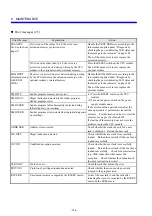
When the indicator indicates one of the following messages, troubleshoot the S10mini by taking
action as described for that message.
Message
Action
ROM IDLE
Hold down the reset switch for at least 20 seconds.
In case when the CPU is not recovered by the above method, clear all the
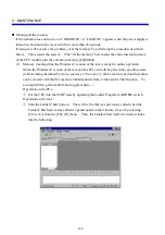
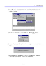
memory by following “Clearing all the memory” on page 106.
NST OVER
The nesting level of the ladder diagram program is five or more. Correct the
program so that it will not go more than four levels deep.
PROT ERR
An attempt was made to write a user-created C program to a protected area in
memory. Take actions (1) and (2) below.
(1) Check the program and correct its errors.
(2) When the program needs to be written to that area, set the PROTECT
switch to OFF.
IO-F-
∆∆∆
The fuse at I/O address Y
∆∆∆
is blown. Replace the fuse at Y
∆∆∆
.
IO-T-
∆∆
0
The remote I/O data at I/O address
∆∆
0 could not be transferred. Check the
power supply, wiring of the remote I/O cable, termination, and the station
number.
LED OFF
Hold down the reset switch for at least 20 seconds.
In case when the CPU is not recovered by the above method, clear all the
memory by following “Clearing all the memory” on page 106.
Summary of Contents for S10mini D
Page 1: ......
Page 14: ...THIS PAGE INTENTIONALLY LEFT BLANK ...
Page 19: ...1 BEFORE USE ...
Page 28: ...THIS PAGE INTENTIONALLY LEFT BLANK ...
Page 29: ...2 OVERVIEW ...
Page 34: ...THIS PAGE INTENTIONALLY LEFT BLANK ...
Page 35: ...3 NAMES AND FUNCTIONS OF PARTS ...
Page 45: ...4 INSTALLATION ...
Page 54: ...THIS PAGE INTENTIONALLY LEFT BLANK ...
Page 55: ...5 WIRING ...
Page 68: ...THIS PAGE INTENTIONALLY LEFT BLANK ...
Page 69: ...6 SETTING ...
Page 84: ...THIS PAGE INTENTIONALLY LEFT BLANK ...
Page 85: ...7 OPERATION PROCEDURES ...
Page 91: ...8 EXPLANATION OF OPERATION ...
Page 111: ...9 MAINTENANCE ...
Page 128: ...THIS PAGE INTENTIONALLY LEFT BLANK ...
Page 129: ...10 SPECIFICATIONS ...

