MAN3186 - TITANUS MICRO
•
SENS®
20
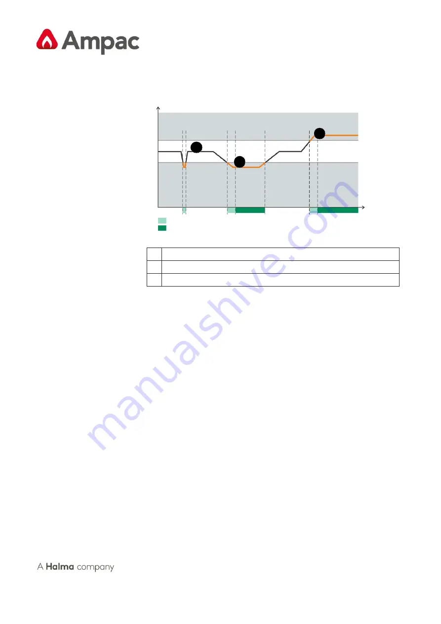
After a programmable delay time has elapsed, the fault is displayed on the
TITANUS MICRO·SENS® and a corresponding fault message is forwarded
via a fault contact to any connected FDCP. The trigger thresholds for the
monitoring window can be adapted to the ambient conditions.
3
Trigger
threshold
1
Target value
2
Trigger
threshold
Time
Adjustable delay time
Fault message
Image 4:
Example of signal path air flow sensor fault
1
Normal air flow
2
Air flow too low (blockage)
3
Air flow too high (rupture)
Air flow calibration
An automatic, air pressure-independent air flow calibration is carried out on
the TITANUS MICRO·SENS® after the detection unit has been installed in
the device base. In addition, calibration by means of a diagnostic tool is
possible. This can be used to carry out air pressure-dependent or -
independent air flow calibration.
To adjust the TITANUS MICRO·SENS® to the typical air flow of the pipe
network, the air flow initialisation process needs to be performed. This has to
be done for each device once during commissioning, after making changes
to the pipe system planning and after changing the fan voltage.
During the air flow initialisation process, the device initially saves the
measured actual value of the air flow as a target value via the integrated air
flow monitoring. This target value serves as reference value for the further
evaluation of a potential air flow fault. Depending on the selected trigger
threshold, the current air flow value may fluctuate around this target value
Si
g
n
a
l
of
t
h
e
a
ir
f
lo
w
se
n
so
r
Summary of Contents for Ampac TITANUS MICRO-SENS
Page 229: ......


