background image

Chapter 8: System Hardware Overview 

5495975-1EN Rev.9

8-75

© 2013-2017 General Electric Company. All rights reserved.

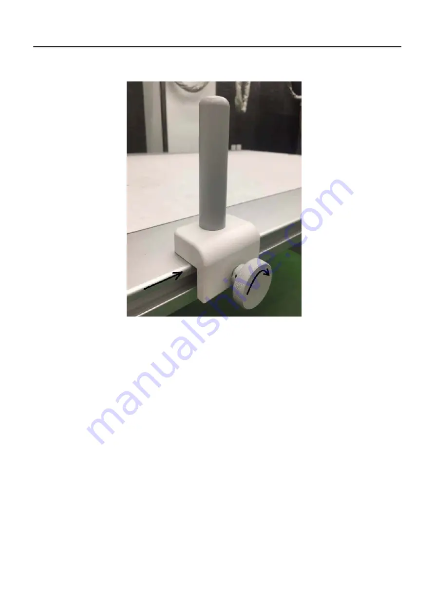
Figure 8-56  

Clamp and hand grip locked

Remote Control 

The remote control allows you to set the field of view, manually collimate, or enable the collimator lamp, 
also allows you to move the Wallstand Receptor. Refer to  

Table 8-16

 for details.

1. Aim the remote directly at the Wallstand Display.

For Collimator (FOV) and Tube positioning, aim the remote at the sensor area of the Wallstand Dis-
play. (Refer to 

Figure 8-57

)

Summary of Contents for Optima XR646

Page 1: ... 1EN Rev 9 2013 2017 General Electric Company All rights reserved Optima XR640 Optima XR646 Digital Radiographic System Operator Manual 5495975 1EN Rev 9 2013 2017 General Electric Company All rights reserved ...

Page 2: ...5495975 1EN Rev 9 2013 2017 General Electric Company All rights reserved ...

Page 3: ... x radiation causes damage to human tissue Therefore adequate precautions must be taken to prevent unauthorized or unqualified persons from operating this equipment or exposing themselves or others to its radiation Before operation persons qualified and authorized to operate this equipment should be familiar with the recommendation of the International Commission on Radiological Protection contain...

Page 4: ...78530 BUC FRANCE Green QSD 1990 Standard issued by MDD Medical Devices Directorate Department of Health UK Medical Device Good Manufacturing Practice Manual issued by the FDA Food and Drug Administration Department of Health USA Underwriters Laboratories Inc UL an independent testing laboratory Canadian Standards Association CSA International Electrotechnical Commission IEC international standards...

Page 5: ...e sold by the below names and be manufactured by the below manufactur ers Model Name Manufacturer Manufacturing Site Manufacturer address Optima XR646 GE HUALUN MEDICAL SYSTEMS CO Ltd No 1 Yong Chang North Road Beijing Economic Technological Development Zone BEIJING 100176 CHINA GE MEDICAL SYSTEMS LLC 3000 North Grandview Blvd WAUKESHA WI 53188 UNITED STATES ...

Page 6: ...pecifications in Chapter 7 Modify Image pasting drawing of illustration of acquisition in Chapter 13 Update Power Supply Conditions in Appendix B Specifications 4 21 July 2015 Add a warning explanation to patient load label in Chapter 2 Delete United states from United states Federal law restricts this device to sale by or on the order of a physician in Chapter 1 and Chapter 2 Flash Pad Detector U...

Page 7: ... Digital Wallstand added word digital in several places in order to differen tiate Digital Wallstand with new Manual Wallstand added Wallstand chin rest as applied part Added a new section Manual Wallstand after section Digital Wall stand In section Digital Table added word digital in several places in order to dif ferentiate Digital Table with new Standard Table revised a Caution of item 7 in tab...

Page 8: ...section Wireless Regulatory Information under section UWB Compliance Statement Added a Caution under section General Use Warnings Added a symbol under section Special Notices Added a Caution under section Patient Positioning Warnings 3 In chapter 5 Added a Caution under section General Acquisition 4 In chapter 8 Revised Figure 8 36 and added a warning under section Remove or Attach the Lateral Pos...

Page 9: ...ment 2 4 IEC Equipment Classifications 2 4 UWB Ultra WideBand Compliance Statement 2 4 Wireless Regulatory Information For EU 2 7 Wireless Parts Included 2 7 Accessories Software 2 7 EU Authorized Representative 2 8 Safety Design in Wireless Link 2 8 Declaration of Conformity for RED 2 8 Electromagnetic Compatibility 2 9 Radiation Safety 2 14 Radiation Protection 2 15 Monitoring of Personnel 2 15 ...

Page 10: ...Disposal of Waste 2 44 Battery Disposal 2 44 Pollution Control Label 2 45 Dose Chart 2 46 X ray Source Assembly Filtration 2 47 Dose DAP Indication 2 47 Environmental protection 2 48 Chapter 3 Pediatrics and small patients Pediatric Use 3 1 Optimize Pediatric Protocols for your facility 3 1 What Do I Need to Know About 3 2 Radiation Exposure Sensitivity 3 2 Suggestions for Minimizing Unnecessary D...

Page 11: ...p button 5 1 Raise and Lower the Digital Table 5 1 Position the Table Longitudinally and Transversely 5 2 Adjust the Overhead Tube Suspension OTS Position 5 3 Adjust the Tube Position 5 3 Rotate the Multi Leaf Collimator 5 4 General Acquisition 5 4 Manual Patient Entry Worklist 5 6 Add Patient 5 6 Edit Patient Information 5 6 Chapter 6 Status Bar Overview 6 1 Digital Detector Status 6 4 Chapter 7 ...

Page 12: ...1 Physical Characteristics 7 21 Communication 7 22 Environmental Constraints 7 22 Chapter 8 System Hardware Overview Configurations 8 1 Component Identification 8 2 Available Accessories 8 4 Acquisition Workstation 8 5 Radiology Control Interface Module RCIM 8 6 Hand Switch 8 9 High Throughput Mode 8 10 Mouse Controls 8 10 Bar Code Scanner Option 8 11 Overhead Tube Suspension OTS 8 12 OTS User Int...

Page 13: ...eral Positioning Bar 8 41 Ion Chambers 8 42 Manual Wallstand 8 44 Position the Receptor 8 46 Vertical Adjustment 8 46 Vertical Adjust Handle 8 47 Insert or Remove Grids 8 47 Positioning Bars and Hand Grips 8 49 Remove or Attach the Lateral Positioning Bar 8 49 Ion Chambers 8 50 Mobile Table 8 50 Digital Table 8 51 Components 8 51 Raise and Lower the Digital Table 8 54 Position the Table Longitudin...

Page 14: ...ssories 8 84 Cross Table Holders 8 84 Weight Bearing Stand Option 8 84 Lateral Bridge Lengths 8 85 Chapter 9 Worklist Overview 9 1 Patient List Columns 9 5 Manage List Find Procedures 9 6 Search 9 6 Sort by Column 9 6 Filter List 9 7 Refresh 9 10 Manual Refresh 9 10 Auto Refresh 9 10 Select Procedures 9 11 Select a Single Procedure 9 11 Select Multiple Procedures 9 11 Delete Procedures 9 12 Delete...

Page 15: ...27 AEC Limitation Messages 10 29 Acquire AEC Images 10 30 End Exam 10 31 Suspend 10 31 Close 10 31 Discontinue 10 31 Image Recovery 10 32 Chapter 11 Image Viewer Overview 11 1 Tool Selection List 11 4 Select Images 11 5 Change Viewing Format and Size 11 6 Adjust Images 11 7 Annotate and Mask Images 11 9 Customize System Annotations 11 12 Add Image Annotations 11 13 Delete Image Annotations 11 14 A...

Page 16: ...Host 12 7 Copy Images to Another Exam 12 8 Copy Exams to a CD or DVD 12 9 Delete Exams Series or Images 12 11 Lock Exams from Deletion 12 11 Unlock Exams 12 12 Make Exam Anonymous De Identify 12 12 Chapter 13 Advanced Applications Dual Energy 13 1 Overview 13 1 Acquisition and Images 13 1 General Guidelines 13 2 Technique Settings and Image Quality for Chest Exams 13 2 Patient Size 13 2 High kVp 1...

Page 17: ... Wallstand Exam 13 19 Alternate Auto Image Paste Acquisition Workflows 13 24 Leg Paste at wallstand 13 24 Image Viewer 13 25 View Pasted Composite Image 13 26 Select Images 13 26 Re Process Images 13 27 Re paste 13 27 Change Looks Processing Vertical Equalization 13 30 Print Pasted Images 13 31 Preferences 13 31 Configure Default Print Auto Print Settings 13 31 Add or Edit Auto Image Paste Protoco...

Page 18: ... Detector Identified By Color and Shape 15 15 Detector System List 15 16 Detector Sleep Time 15 16 Worklist 15 17 Default Query 15 17 Auto Refresh 15 19 Preset Names 15 19 Add Preset Names 15 20 Edit Preset Names 15 20 Remove Preset Names 15 21 Image Management 15 21 Retry Failed Print 15 22 Copy Exam 15 22 Auto Tag Quality Check 15 22 Auto Print 15 23 Orthopedic Magnification 15 24 Auto Send Auto...

Page 19: ... TE Usage 15 55 Over penetrated Regions 15 55 Under penetrated Regions 15 55 TE Parameters 15 56 Area 15 56 Strength 15 57 Electromagnetic Interference EMI Reduction 15 58 Overview 15 58 Gird Line Reduction Single Energy 15 59 Repeat Reject Analysis RRA 15 60 Health Page 15 60 To View Detector Bump Event Report 15 61 Time Stamp 15 63 Appendix A Login Administration Enabling EA3 Login A 1 Understan...

Page 20: ...ups A 10 Add a Local Group A 11 Add a Enterprise Group A 12 Manage a Group A 13 Remove a Group A 13 Change Group s Roles A 14 Add Memberships A 14 Remove Memberships A 14 Configure Enterprise Tab A 14 Auto Configuration A 16 Manual Configuration A 17 Field Highlighting for changes A 18 Appendix B Specifications ...

Page 21: ...Table of Contents 5495975 1EN Rev 9 TOC 13 2013 2017 General Electric Company All rights reserved This page intentionally left blank ...

Page 22: ...ad and understand the contents of this manual before attempting to use this product This chapter explains the purpose and design of this Operator Manual It provides information on the organization chapter format and graphic conventions that identify the visual symbols used throughout the manual How to access the electronic version of a manual on a website The Operator Manual is available through t...

Page 23: ...ion library Scope Of This Manual This manual is intended for health care professionals trained in radiological science and is intended to introduce you to the system components and features It is not intended to teach radiological science or make any type of clinical diagnosis Prerequisite Skills This guide is not intended to teach radiology It is necessary for you to have sufficient knowledge to ...

Page 24: ...guide uses the international symbol along with the danger warning or caution message This section also describes the purpose of a Note DANGER Danger is used to identify conditions or actions for which a specific hazard is known to exist which will cause severe personal injury death or substantial prop erty damage if the instructions are ignored WARNING Warning is used to identify conditions or act...

Page 25: ...wn list Activating a tab Highlighting row items Click START EXAM Clicking a button on a workstation screen Press ENTER Pressing a hard key on the keyboard Press CTRL ALT DELETE Pressing a combination of keys on the keyboard The key that should be clicked first is listed first Click and hold SHIFT Clicking and holding down a hard key on the keyboard In the Matrix text box The name of text box in wh...

Page 26: ... performs a specific action such as opening a new screen or saving settings A group of two or more buttons provides a choice of settings such as which acquisition mode is active The dark blue color indicates which button or buttons are selected A single button to start an exam Two buttons to select the acquisition mode Drop down list Drop down lists open to reveal several options but only one opti...

Page 27: ...g on another tab hides the previous information and reveals a different set of information A tab to move between two screens Checkbox Checkboxes indicate selection A single checkbox shows that an option is active Multiple checkboxes show that several options are selected A single checkbox Multiple checkboxes Text box Text boxes allow information to be entered using the keyboard Text boxes Table 1 ...

Page 28: ... persons carelessly exposing themselves or others to radiation It is important that everyone having anything to do with x radiation be properly trained and fully acquainted with the recommendations of the National Council on Radiation Protection and Measurements as published in NCRP Reports available from NCRP Publications 7910 Woodmont Avenue Room 1016 Bethesda Maryland 20814 and of the Internati...

Page 29: ...hnologies authorized service representatives The equipment must be used in accordance with the instructions for use WARNING This X Ray unit may be dangerous to patient and operator unless safe exposure factors operating instructions and maintenance schedules are observed CAUTION To be used by authorized personnel only WARNING Electric Shock Hazard Do not remove covers or panels The Acquisition Con...

Page 30: ...tective earth CAUTION Restrict access to the EQUIPMENT in accordance with local regulations for RADIATION PROTECTION CAUTION Do not lay any object on the cabinets that would restrict air flow from the top of the cabinet CAUTION Always be alert to safety when you operate this equipment You must be familiar enough with the equipment to recognize any malfunctions that can be a hazard If a malfunction...

Page 31: ... 2 28 IEC 60601 2 54 IEC 60601 1 3 UWB Ultra WideBand Compliance Statement For Japan The frequency band used for the UWB radio function is also used for radio equipment of other radio systems The use of equipment with UWB radio function shall be limited to indoors i e within envi ronments such as houses apartments buildings etc Not approved for outdoor use Even when used indoors such as at broadca...

Page 32: ...bility of exceeding the FCC radio fre quency exposure limits you should keep a distance of at least 20 cm between you or any other person in the vicinity and the antenna Interference Statement These devices comply with Part 15 of the FCC Rules Operation of the devices is subject to the following two conditions The devices may not cause harmful interference The devices must accept any interference ...

Page 33: ...ed to indoors i e within environ ments such as houses apartments buildings etc Not approved for outdoor use For New Zealand The frequency band used for the UWB radio function is also used for radio equipment of other radio systems 1 The use of equipment with UWB radio function shall be limited to indoors i e within envi ronments such as houses apartments buildings etc Not approved for outdoor use ...

Page 34: ...reless Regulatory Information For EU Wireless Parts Included The following wireless parts are included in this product Accessories Software Table 2 1 Item Name Function GE P N Frequency Band Transmit Power 1 UWB Host Dongle UWB host interface to system workstation 5397317 5 6 GHz 9 GHz 41 3 dBm MHz 2 URP Wireless Detector Wireless detector for X_ray imaging 5340000 7 6 GHz 9 GHz 41 3 dBm MHz ...

Page 35: ... or the inter ference stops Wired connection tether mode is provided as a backup option when the RF environment cannot support a reliable wireless link Declaration of Conformity for RED The wireless parts listed above are CE marked according to the provisions of the RED Directive 2014 53 EU GE Medical Systems LLC here by declares that these parts are in compliance with the essential requirements a...

Page 36: ...list or image viewer screens the system may recover by itself or you may need to reboot the system the system may shut itself down and will require a reboot CAUTION A power surge during image transmission to the workstation after acquisition may cause the image to be lost WARNING When trying to fix the monitor video loss or inoperable mouse issues cycling the system power on off may cause the moni...

Page 37: ... further suggestions Use of accessories transducers cables and other parts other than those specified by the manufacturer of this equipment may result in increased emissions or decreased immunity of the equipment The manufacturer is not responsible for any interference caused by using other than recommended interconnect cables or by unauthorized changes or modifications to this equipment Unauthori...

Page 38: ...f different cable lengths are required contact a qualified service representative for advice 1 Electromagnetic Emission Table 2 3 Guidance and manufacturer s declaration electromagnetic emissions Guidance and manufacturer s declaration electromagnetic emissions The Optima XR646 is intended for use in the electromagnetic environment specified below The customer or the user of The Optima XR646 shoul...

Page 39: ...s 2 kV for power supply lines 1 kV for input output lines Mains power quality should be that of a typical commercial or hospital environment Surge IEC 61000 4 5 1 kV differential mode 2 kV common mode 1 kV differential mode 2 kV common mode Mains power quality should be that of a typical commercial or hospital environment Voltage dips short interruptions and voltage variations on power supply inpu...

Page 40: ...recommended separation distance in metres m Field strengths from fixed RF transmitters as determined by an electromagnetic site surveya should be less than the compliance level in each frequency rangeb Interference may occur in the vicinity of equipment marked with the following symbol NOTE 1 At 80 MHz and 800 MHz the higher frequency range applies NOTE 2 These guidelines may not apply in all situ...

Page 41: ...tic environment in which radiated RF disturbances are controlled The customer or the user of The Optima XR646 can help prevent electromagnetic interference by maintaining a minimum distance between portable and mobile RF communications equipment transmitters and The Optima XR646 as recommended below according to the maximum output power of the communications equipment Rated Maximum Output Power P ...

Page 42: ...uirements at your site please refer to your Local Radiation Protection Rules as provided by your Radiation Protection Advisor CAUTION While operating or servicing x ray equipment always keep a distance not less than 2 meters from the focal spot and X ray beam protect body and do not expose hands wrists arms or other parts of the body to the primary beam Monitoring of Personnel Monitoring of person...

Page 43: ...ss and attempts to save all data acquired prior to the abort Use the Emergency Stop button for patient related emergencies System Emergency Off Button when pressed the power to all system components is removed stopping all motion and generation of X rays The system aborts any acquisitions in progress and data obtained prior to the abort can become corrupt or lost Use the System Emergency OFF butto...

Page 44: ...RNING It is the responsibility of the owner to make certain that only properly trained fully qualified personnel are authorized to operate the equip ment A list of authorized operators should be maintained WARNING Check for obstructions before moving the system table gantry or other do not drive the system into or onto fixed objects WARNING If applicable patient connected lines tubes etc shall be ...

Page 45: ...stationary items likely to be in the environment WARNING Perform periodic maintenance to ensure continued safe use of the equipment Follow recommended preventative maintenance schedule as outlined in the GE Field Service Manual CAUTION Collision with the OTS may cause minor injury Ensure there is no one in the path of the OTS during positioning CAUTION Make sure any other accessories or materials ...

Page 46: ... in the x ray beam Table 2 7 Maximum Attenuation Equivalent mm AL CAUTION Residual radiation hazard Do not stand behind image receptor Item mm Al Image Pasting patient barrier 0 08 Non elevating table 1 0 Non elevating table with carbon fiber table top 1 0 Digital elevating table with floating table top 0 7 Weight Bearing Stand 1 08 Standard elevating table with floating table top 1 0 Manual Walls...

Page 47: ...r radiation Do NOT stare into beam When you switch on the linear laser light localizer make sure no person looks directly into the laser to avoid eye injuries or impaired vision Peak power 1 mw wave length 540 700 nm class II laser product Figure 2 3 Collimator laser label CAUTION Use of controls or adjustments or performance of procedures other than those specified herein may result in hazardous ...

Page 48: ... injury may result CAUTION The technologist must remain close to the patient when the remote con trol is in use WARNING The digital table maximum supported weight with full tabletop func tionality is 320 kg 705lbs Exceeding the limit may cause equipment damage or injury to the patient WARNING The standard table shall have a maximum evenly distributed load capa bility of 250kg 552lbs Exceeding the ...

Page 49: ...l on the bar CAUTION The operator can t change detector connection mode before the image is displayed on monitor after exposure Tabletop Motion Warnings CAUTION When the power to the table is off the tabletop can move freely To avoid injuries monitor the tabletop movement WARNING Prior to raising or lowering the tabletop ensure there are no obstruc tions present above or below CAUTION Before the p...

Page 50: ...Chapter 2 Safety and Regulatory 5495975 1EN Rev 9 2 23 2013 2017 General Electric Company All rights reserved Figure 2 4 Table pinch point ...

Page 51: ... range of 0 50º C 32 122 F Pinch Points and Crush Hazard Summary This section lists the potential pinch points or crushing hazards that exist for various compo nents of the system Table 2 8 Pinch Points and Crush Hazard Summary Component Warning Table WARNING Potential Pinch Point Use table foot pedals with care when lowering the table Clearance is limited next to the table side cover and a pinch ...

Page 52: ... the multi leaf collimator in such a way that neither hand can be pinched or crushed between the han dles and the collimator Wallstand CAUTION Hand Crush Hazard Keep your extremities and the patient s extremities away from the pinch areas and the top of the wallstand arm when tilting the wallstand receptor Acquisition Workstation CAUTION Potential Pinch Point The DVD CD tray can open and close aut...

Page 53: ...eight limit Damage to equipment or injury may occur if the maximum weight is exceeded Operating temperature This symbol indicates that the component must be within a minimum and maximum temperature range in order to operate Damage to equipment may occur if equipment is used at temperatures outside of the specified range Emergency Stop Button It s used to immediately power down the system including...

Page 54: ... Operational symbols Symbol Description X ray emission is used to indicate the X ray tube head is emitting X rays Take adequate precautions to prevent the possibility of any persons carelessly unwisely or unknowingly exposing themselves or others to radiation X ray source assembly is used to indicate a reference to an X ray source assembly X ray tube is used to indicate a reference to the X ray tu...

Page 55: ...tors associated with the selection of focal spot or the connection for the corresponding filament When used with the small focal spot symbol this symbol applies to the larger focal spot When used with the large focal spot symbol this symbol applies to the smaller focal spot Identifies controls or indicators associated with the selection of a large focal spot or the connection for the corresponding...

Page 56: ... 12 Electrical type Symbol Description Type B Equipment indicates the equipment provides a particular degree of protection against electrical shock regarding leakage current and protective earthing per IEC60601 1 Table 2 13 Electrical current types Symbol Description Alternating Current indicates the equipment is suitable for alternating current only Direct Current indicates the equipment is suita...

Page 57: ...clean earth ground identifies any terminal of a specially designed earthing system where noise from earth of leads will not cause a malfunction of the equipment Protective earth ground identifies any terminal which is intended for connection of an external protective conductor to protect against electrical shock in case of a fault Frame or chassis identify the frame or chassis terminal Equipotenti...

Page 58: ...ntrol for indicating radiation field by using light Identifies controls for opening the collimator blades or indicates partially or fully open state Identifies controls for closing the collimator blades or indicates closed state Indicates the collimator blades are closed The controlled blades are shown in thicker lines Indicates the collimator blades are open The controlled blades are shown in thi...

Page 59: ...of largest column X ray Tube Casing MX100 09PS 46 155400G285 Rear of X ray tube X ray Tube Insert 6 1 25 12 5 degree MX100 2336058 Rear of X ray tube Collimator 5234954 5730663 Rear of collimator Workstation PC Z420 5843000 3 5843001 3 Top front of PC Optima XR646 System Rating Plate 5502131 Top of system cabinet System rating plate for Optima XR646 WSO 5730354 Top front of PC System Cabinet 53970...

Page 60: ...ital Table Warning Labels Digital Wall Stand GCWS C1 standard arm GCEWS C1 extended arm Left side of carriage Manual Wallstand GCMWS C6 Left side of carriage Standard Table GCTBL C6 Right side Wall Stand Ion Chamber 5143310 3 cell 5261064 4 cell Inside wall stand detector housing Flash Pad Detector URP 5340000 7 Top of unit Tether Interface Box 5394349 Under cover on right side Detector BIN 539434...

Page 61: ...Regulatory 5495975 1EN Rev 9 2 34 2013 2017 General Electric Company All rights reserved Figure 2 6 Digital Table Warning Label Table 2 17 Digital Table warning Labels Icons Item Description Label 1 Table pinch point label ...

Page 62: ...he table is less than or equal to 320 kg 706 lbs and the tabletop is positioned in the center 3 The table cannot be moved vertically and the tabletop shall be positioned in the center when the distributed load over the table is more than 320 kg 706 lbs and less than or equal to 400 kg 882 lbs WARNING When the patient weight exceeds 220 kg 485 lbs then patient on off load of the table should only o...

Page 63: ...5495975 1EN Rev 9 2 36 2013 2017 General Electric Company All rights reserved Standard Table Warning Labels Figure 2 7 Standard Table Warning Label 4 Tray load label Table 2 17 Digital Table warning Labels Icons Item Description Label ...

Page 64: ...load is less than or equal to 180kg 397lbs located in the center of the tabletop end and the tabletop is positioned in the center 2 The table can be moved vertically when the distributed load over the table is less than or equal to 250kg 552lbs and the tabletop is positioned in the center CAUTION When the patient weight exceeds 180kg 397lbs then patient on off load of the table should only occur f...

Page 65: ...c Company All rights reserved OTS Label 3 Inhibition warning label 4 Clamp Hand label 5 Tray Symbol Note This symbol indicates that the tray moved out can t support the body extremities weight for X_ray exposure Table 2 18 Standard Table warning Labels Icons Item Description Label ...

Page 66: ...er 2 Safety and Regulatory 5495975 1EN Rev 9 2 39 2013 2017 General Electric Company All rights reserved Figure 2 8 OTS Label Collimator Label Figure 2 9 Collimator Label Figure 2 10 Collimator Caution Label ...

Page 67: ...Chapter 2 Safety and Regulatory 5495975 1EN Rev 9 2 40 2013 2017 General Electric Company All rights reserved ...

Page 68: ...ety and Regulatory 5495975 1EN Rev 9 2 41 2013 2017 General Electric Company All rights reserved Lateral Bar Label Figure 2 11 Lateral Bar Label Maximum Load Allowed 30 kgf Keyboard Label Figure 2 12 Keyboard Label ...

Page 69: ...e used by authorized personnel only UDI Label Every Optima XR646 system has an unique marking for identification The Unique Device Identification UDI marking appears on the product label which is located on system cabinet UDI Unique Device Identifier A UDI is an unique numeric or alphanumeric identification code assigned to medical devices by the manufacturer of the device An unique device identif...

Page 70: ...nce caused either by the use of interconnect cables other than those recommended or by unauthorized changes or modifications to this equipment Unauthorized changes or modifications could void the user s authority to operate the equipment Note To comply with the regulations applicable to an electromagnetic interface for a Group 1 Class A Medical Device all interconnect cables to peripheral devices ...

Page 71: ...the battery must be recycled or disposed of in accordance with local or country laws The letters below the separate collection symbol indicate whether certain elements Pb Lead Cd Cad mium Hg Mercury are contained in the battery To minimize potential effects on the environ ment and human health it is important that all marked batteries that you remove from the product are properly recycled or dispo...

Page 72: ...ained in electronic information products will not leak or mutate under normal operating conditions so that the use of such electronic infor mation products will not result in any severe environmental pollution any bodily injury or damage to any assets The unit of the period is Year In order to maintain the declared EFUP the product shall be operated normally according to the instructions and envir...

Page 73: ... as possible CAUTION If no technical factors are present in the system for any view the default settings are kV 40 ma 25 mAs 0 25 SID 100cm Grid In These values are placeholders only No exposures should be made until the user selects values appropriate for the patient size Table 2 19 Dose Chart Expected receptor Default Dose µGy at 80 kVp is less than Equivalent Film Speed 16 00 100 12 90 125 10 0...

Page 74: ...ted by calculation They are displayed on the image viewer for each exposure The Dose value is calculated at the position of patient entrance Figure 2 18 Block diagram for Dose DAP calculation The nominal Dose is calculated at the calibrated distance based on exposure techniques such as mAs kVp and additional filtration The final patient entrance dose is got by correcting with SID and tube angle an...

Page 75: ...neral Electric Company All rights reserved Environmental protection With the disposal of waste products residues and equipment accessories that are out of their expected service life to avoid the impact of environment please comply with local statute or call GE Service ...

Page 76: ...Chapter 2 Safety and Regulatory 5495975 1EN Rev 9 2 49 2013 2017 General Electric Company All rights reserved This page intentionally left blank ...

Page 77: ...rs on a child as used on an adult may result in larger doses to the child X ray settings can be adjusted to reduce dose significantly while maintaining diagnostic image quality Optimize Pediatric Protocols for your facility The protocols supplied with the system represent examples for procedures commonly conducted in radiography Based on the needs of a particular practice these protocols may be mo...

Page 78: ... should be carefully considered prior to each exposure Follow your facility imaging guidelines to determine appropriate collimation Properly Center All Patients In addition to collimation centering of intended anatomy should be considered This is especially true when utilizing AEC ion chambers Improper centering over ion chambers may cause more or less than the desired dose which may lead to overe...

Page 79: ...esired image quality Figure 3 1 Patient Size Once patient size is selected further adjustments to kVp MAS Filtration and Grid can be made to further minimize patient dose Automatic Exposure or Fixed Exposure Consideration should be made when utilizing Automatic Exposure AEC or Fixed Exposure Each protocol on your system has been installed with a preset method of exposure however GE recommends revi...

Page 80: ...hnical factors are changed Reference the DEI DI section of this operator manual for more information Protocol Database Edit In collaboration with your Radiologist and Physicist protocol techniques can be changes as a default on your system This should not replace observing the technical acquisition screen carefully prior to each exposure but can assist in displaying an appropriate range of techniq...

Page 81: ...General Information This chapter explains some of the basic operations and features of the system such as how to start up and shutdown the system software how to login and log off and how to view system status and mes sages Refer to Chapter 8 System Hardware Overview for information about identifying system components ...

Page 82: ...tes Refer to System Emergency OFF Buttons p 4 10 for more information Start Up 1 Press the Power On button on the RCIM Radiology Control Interface Module Figure 4 1 Power button on RCIM 2 Wait a few minutes until the entire system is powered The system powers up automatically If enabled the Login screen appears on the monitor when the system is ready Refer to Login and Log off p 4 4 for more infor...

Page 83: ...1 for more infor mation 2 Click the UTILITY button at the top of the Worklist screen Figure 4 2 Utility button 3 Select System on the Utilities screen Figure 4 3 Utilities System screen 4 Click SHUTDOWN A message appears The system will be shut down NOTE Please allow for the tube fan speed to slow if running high before shutting down system 5 Click YES to proceed with shut down The system powers o...

Page 84: ... on administering the login function Standard Login The Login screen Figure 4 4 appears when the system is started reset and after a user logs off The sys tem may also be configured to display the Login screen if the system has been inactive for a specified period of time inactivity timeout Figure 4 4 Example login screen Follow this process to login to the system 1 Start up the system or log off ...

Page 85: ... xYz is not the same pass word as Xyz 3 Click LOGIN Contact your technical support group or system administrator if you still are not able to login Emergency Login Emergency Login is a HIPAA required function to allow quick access to medical systems in the event of an emergency Depending on the system s configuration this option may not be available Refer to Appendix A Login Administration to conf...

Page 86: ...efer to Appendix A Login Administration to configure the inactivity time out function To access the system screens follow the Standard Login or Emergency Login process described above Log Off 1 Close suspend or discontinue any open exams if necessary Refer to Chapter 10 Image Acquisition End Exam p 10 31 for more information 2 Close the Image Viewer if necessary 3 Click LOGOFF at the top of the Wo...

Page 87: ... SID detents the Exposure Hold icon will appear on the OTS user interface and at the Acquisition workstation screens Select the Exposure Hold icon for detailed description on the inhibit condition Note This interlock is no longer active when the tube angle is 10 degrees Tube Pivot Interlock The Tube Pivot interlock LED illuminates when the tube pivot must be rotated to 0 degrees normal posi tion F...

Page 88: ... informing you of the table lock Exposures will be inhibited until the lock is resolved To unlock the table top 1 Release the Table top positioning foot pedal if necessary Figure 4 7 Table top positioning foot pedal 2 Remove hands fingers or other object from under the table edge 3 Press the table top positioning foot pedal Figure 4 7 two consecutive times double tap 4 Hold the foot pedal down and...

Page 89: ... emergency stop and to reset the Emergency Stop button 1 In an emergency situation press the Emergency Stop button in with force 2 Resolve the emergency situation CAUTION For Digital table when the Emergency Stop button has been activated the table will move longitudinally only The table is not locked into position Exercise extreme caution with your patient when this happens 3 When normal conditio...

Page 90: ...t least one Emergency OFF button near the doorway of every room in the system scan suite Ask your supervisor to show you the location of all the Emergency OFF buttons in the system suite Follow facility guidelines to report an emergency Press the System Emergency OFF button red circular button located on the wall in the event of a catastrophic emergency such as fire or earthquake System Reset Shou...

Page 91: ...gin screen or Worklist screen will appear depending on how your system is configured when the system is ready Refer to Start Up p 4 2 for more infor mation Tube Warm Up To extend the life of the tube tube warm up should be done if no exposures have occurred within two hours A warning icon will display when tube warm up is needed CAUTION Initiating an exposure when the X ray tube is cold may damage...

Page 92: ...ector during tube warm up The system will attempt to mis align the tube and the detector but you may need to manually move the tube so that the detector is not exposed during the warm up sequence Pay close attention to system message information for instructions to manually move the detector Exposing the detector may cause a burned in image artifact Table 4 1 Warm Tube functions Function Descripti...

Page 93: ...ng is not recommended as a pri mary method of image identification because of potential user error in identifying anatomical regions Image Markers Image markers e g lead markers are commonly used in identifying radiographs If image markers are placed in regions of direct radiation saturation there is a possibility they can be processed out of the image during image processing Saturated areas beyon...

Page 94: ...tem lets authorized Service Engineers and Applications Specialists located at GE Health care Service Support Centers access X ray systems with your permission to provide the following ser vices Faster Emergency Service response Customer Applications training support System troubleshooting and diagnostics Accumulate system information for failure analysis resolution and prediction to assist in main...

Page 95: ...Chapter 4 General Information 5495975 1EN Rev 9 4 15 2013 2017 General Electric Company All rights reserved Figure 4 13 iLinq Main Screen ...

Page 96: ...stem using the iLinq system Settings The Settings page allows you to enter the default contact information that will display on the Contact GE Form This includes a list of Contacts System ID Phone Number Messages Receives messages from the Online Center Tip Virtual Assist A tool which offers live Clinical Applications training support Contact your Applications Specialist or Sales Representative fo...

Page 97: ...ed Figure 4 14 iLinq Contact GE screen Use this procedure to connect to the iLinq system when you need to report a problem with your system 1 Click the iLinq icon on the Worklist or Acquisition screens 2 Click CONTACT GE 3 Enter the required information into the Contact GE iLinq screen 4 Click Submit Form ...

Page 98: ...rvice Contract The presence of the GE iLinq system alone at a your site does not provide you any rights or title to the iLinq system or any license or right to access use or decompile the iLinq system Any access to or use of the iLinq system beyond the conditions specified in the iLinq Agreement or GE Service Contract or any decompilation of the iLinq system by anyone other than GE personnel is pr...

Page 99: ...ble the e stop button to reset The system will power up automatically CAUTION For Digital Table when the Emergency Stop button has been activated the table will move longitudinally only The table is not locked into position Exercise extreme caution with your patient when this happens Raise and Lower the Digital Table 1 Release the table lock if necessary 2 To raise the table press the Up pedal two...

Page 100: ...ot pedal two consecutive times double tap This activates the foot pedal 3 Hold the foot pedal down and position the table top You can float the table top in all directions while the pedal remains held down 4 Manually move the tabletop in a longitudinal or transverse direction to the desired position 5 Release the foot pedal to lock the tabletop WARNING When moving the tabletop be careful of where ...

Page 101: ...lease the Lateral Lock Release button 4 Use the All Lock Lock Release button to simultaneously move the OTS in vertical lateral and longitu dinal directions If detents are on and the OTS is in lateral detent the system will maintain the lateral position but move freely in vertical an longitudinal a Press and hold the All Lock Lock Release button on the User Interface b Move the OTS to the desired ...

Page 102: ... the collimator is rotated the image border is adjusted to the maximum size based on the selected collimator FOV CAUTION Always grasp the multi leaf collimator in such a way that neither hand can be pinched or crushed between the handles and the collimator General Acquisition This section outlines the basic acquisition process Refer to Chapter 9 Worklist for more detailed information about adding ...

Page 103: ... on monitor after exposure 11 Make technique adjustments as necessary kV mA Focal spot Cu Filter and Ion chambers AEC mode only 12 Position the patient on the table or in front of the wallstand as appropriate CAUTION If using AEC mode collimation must be active over the ion chambers being used If it is not possible to collimate over the selected ion chambers then FIXED mode should be used in order...

Page 104: ...CAUTION Make sure the patient s name ID number birth date and gender information are entered correctly 3 Click SAVE or START EXAM Edit Patient Information Patient information can only be edited if manually entered on system and exam has not started Patient information generated by a HIS RIS cannot be edited on the system 1 Select the procedure from the Worklist 2 Click PATIENT INFORMATION 3 Edit t...

Page 105: ...Chapter 6 Status Bar 5495975 1EN Rev 9 6 1 2013 2017 General Electric Company All rights reserved Chapter 6 Status Bar Overview Figure 6 1 Status Bar Worklist Screen 3 7 8 10 11 4 1 2 5 6 9 ...

Page 106: ...tric Company All rights reserved Figure 6 2 Status Bar Image Management Screen Table 6 1 Status Bar Icons Item Description 1 Inhibits Counter Displayed only when there are available Inhibits Displays actual number of inhibits in the Inhibits Bar 1 2 3 4 6 7 8 9 11 12 ...

Page 107: ...ts the Inhibit Bar it expands and displays a list of all interlocks and error conditions preventing an exposure 3 System Message Bar When the user selects the System Message Bar it expands and displays all previous system status messages since the last system restart 4 Digital Detector icon 5 Warm Tube Refer to Chapter 4 General Information Tube Warm Up p 4 11 for more information 6 QAP Button Ref...

Page 108: ... heat units remaining 9 Secondary Technique Display Displays the technique values that the generator has loaded Note Could be the previous exposure techniques performed 10 iLinq Button Connects to iLinq remote support services Refer to iLinq for more information 11 Transfer Log 12 Image Remaining Icon Description Digital Detector Indicating no less than 50 remaining power Digital Detector Tethered...

Page 109: ... Digital Detector No detector registered to the system Digital Detector Failed Communication Digital Detector DOCKED Discharging Digital Detector Battery 2 green bars 100 50 capacity Discharging Digital Detector Battery 1 green bar 49 25 capacity Discharging Digital Detector Battery 1 yellow bar 24 1 capacity Icon Description ...

Page 110: ...al Detector Battery 2 green bars 100 capacity Charging Digital Detector Battery Toggle between 1 green bar and 2 green bars 51 100 capacity Charging Digital Detector Battery Toggle between 1 yellow bar and 1 green bar 26 50 capacity Charging Digital Detector Battery Toggle between 1 red bar and 1 yellow bar 0 25 capacity Icon Description Digital Detector Tethered Digital Detector No detector regis...

Page 111: ...Chapter 6 Status Bar 5495975 1EN Rev 9 6 7 2013 2017 General Electric Company All rights reserved Digital Detector DOCKED Icon Description ...

Page 112: ...Chapter 6 Status Bar 5495975 1EN Rev 9 6 8 2013 2017 General Electric Company All rights reserved This page intentionally left blank ...

Page 113: ... that converts incoming x ray signal to 14 bit digital data The detector is constructed from a carbon fiber The front Surface contains a graphite x ray imaging win dow The back surface of detector contains safety warnings Detector enclosure is identified as applied part Figure 7 1 Detector Overview Note The back surface of the detector contains screws and should not be imaged or exposed Place this...

Page 114: ...ndling the device use the handle and or use both hands to manipulate the detector into the correct anatomical position for the exam CAUTION Do not swing the device into hard surfaces especially corners as this may scratch the cover create image quality artifacts or damage the electronics inside Special Instructions if the detector is dropped Inspect the exterior for any possible cracks Run Detec t...

Page 115: ...d easily cleanable surface Take care to protect the surface from scratches WARNING Extra precautions should be taken if the device will be exposed to excessive amounts of bodily fluids or liquids The detector is designed to prevent some liquids or particulate matter from getting inside the cover It can sustain a temporary splash or spray but it is not designed to be immersed in liquid not even tem...

Page 116: ... All rights reserved Figure 7 3 Front of the Digital Detector Labels on the front of the digital detector Table 7 1 Front of the Digital Detector Item Description 1 Handles 2 Battery 3 Indicator Lights 4 Power Button 5 Detector Area inside the white marks 6 Antenna inside the detector ...

Page 117: ...gital Detector Back of the digital detector Figure 7 5 Labels on the Back of the Digital Detector Labels on the back of the digital detector Table 7 3 Labels on the Back of the Digital Detector Item Description 1 Centerline 2 Do not defibrillate IEC 5841 w line 3 RF transmitter IEC 5140 4 This side toward X ray source IEC 5338 Item Description 1 FCC Approval and FCC ID Number YYJ 5406102 2 Refer t...

Page 118: ...r removing a load of 110kg onto a 45mm diameter area at any location of the detector front cover When the entire back surface is sup ported the detector will operate within 5 seconds after applying or removing a load of 160kg applied uniformly distributed across the whole detector Item Description 1 Power Button Push to toggle between On and Off mode 2 Indicator Lights 3 Detector ID Insert See Cha...

Page 119: ...tector Base Figure 7 7 Detector Docking Connector Table 7 5 Detector Docking Connector Accessories Battery and Tether The battery and the tether plug share the same connector Only one of these can be plugged in at a time Figure 7 8 Detector Battery and Tether Item Description 1 Detector Docking Connector 1 ...

Page 120: ...e battery pins and patient simultaneously when replacing detector batteries CAUTION The operator should not touch the pins on the detector charging connector and patient simultaneously CAUTION The operator should not touch the pins on the TIB tether connector and patient simultaneously CAUTION The operator should not touch the TIB fuse holder and patient simultaneously WARNING Detector tethered ca...

Page 121: ...ttery charge is necessary for patient imaging Note The battery will also charge while inserted in the detector tray and the tray is completely closed Desktop Battery Charger The desktop battery charger will hold up to two batteries The first battery inserted will be charged first Charging is indicated by a flashing green LED light The second battery will begin to charge when the first one is compl...

Page 122: ...ded insert the battery in the left side or slot of the battery charger Press the calibrate button shown in Figure 7 12 Battery calibration is indicated by a flashing yellow light Figure 7 12 Battery Calibration Detector Charging Bin The Detector Charging Bin is used to charge the battery store the detector and store the detector grid Figure 7 13 Detector Charging BIN Calibrate Button ...

Page 123: ...d attachable tether is 7m in length Optional tether lengths are available in 4m or 10m The tether is used with the digital detector when The detector battery is low The detector is unable to connect to wireless signal Use with Non Wireless Configuration For more information see Appendix B Specifications Figure 7 14 Attachable tether Connection One end connects to TIB and one end connects to detect...

Page 124: ...ound the detector Once together you may handle the grid and detector as one unit The arrows on the grid surface show the direction of the grid lines which run horizontally Figure 7 17 Detector Grid Table 7 6 Detector Grid The system will recognize when the grid is attached Should the grid be attached to the backside of the detector the system will display an exposure inhibit Item Description 1 Gri...

Page 125: ... water or other liquid Do not stand on the grid Do not peel labels or vinyl covering Inspect the grid for physical damage before use Clean the grid regularly between each patient with an approved chemical Refer to Chapter 7 Digital Detector Cleaning p 7 21 for more information Detector Holder The detector holder is used for positioning the detector on the table top Caution should be used when plac...

Page 126: ...er 7 Digital Detector 5495975 1EN Rev 9 7 14 2013 2017 General Electric Company All rights reserved Table 7 7 Detector Holder Detector Holder Detector in Holder Lateral Detector Holder Mobile Detector Holder ...

Page 127: ...econds The detec tor can be turned on by pressing the black power button for one second Detector Alignment To aid in proper alignment of the detector with respect to the X ray source there are alignment marks centered on the front side imaging side of the detector The arrow represents the default head up dis play orientation See Figure 7 18 Figure 7 18 Head Up Arrow Table 7 8 Head Up Arrow Item De...

Page 128: ...een Battery remaining power between 25 and 49 Off Yellow Battery remaining power between 1 and 24 Off Red Battery no remaining power Off Off Detector in sleep mode 2 Wireless Link LED Green Wireless Link Connected Red No Wireless Link Off Detector in sleep mode Note The LED is always Red for Non Wireless Configuration See Appendix B Specifi cations for more information 3 Detector LED Green Detecto...

Page 129: ...Company All rights reserved The various states of the Indicator LED s are shown in the illustrations below Figure 7 20 Battery no less than 50 remaining Wireless link connected Detector ready Figure 7 21 Battery remaining between 25 and 49 Wireless link connected Detector ready ...

Page 130: ...v 9 7 18 2013 2017 General Electric Company All rights reserved Figure 7 22 Battery remaining between 1 and 24 Wireless link connected Detector ready Figure 7 23 Battery no remaining power Wireless link connected Detector exposure not allowed ...

Page 131: ... Detector 5495975 1EN Rev 9 7 19 2013 2017 General Electric Company All rights reserved Figure 7 24 Battery no less than 50 remaining No Wireless link Detector exposure not allowed Figure 7 25 Detector off in sleep mode ...

Page 132: ... a broad low frequency range DC 250kHz It has been found that some common equipment in clinical environments can generate EM fields well over 0 1mG Some measurements have shown 4mG field strengths which can cause artifacts on x ray images EM fields are reduced by the square of the distance between the EM source and the detector Thus mov ing the EM source twice as far away will reduce the field str...

Page 133: ...e been tested and approved by GE for cleaning the detector grid and tether Bleach 50 mix with water 5 8 household Bleach Glutaraldehyde 5 Polyethylene Glycol 20 In the form of Cidex Plus 28 Isopropyl Alcohol 70 concentration Hydrogen Peroxide 15 40 concentration In the form of Diversy Butchers Specifications Physical Characteristics Single panel non tiled amorphous silicon detector with a Cesium l...

Page 134: ...te 480Mbps Effective Throughput 30 70Mbps Standards WiMedia PHY spec v1 2 WiMedia MAC spec V1 0 Certified Wireless USB spec v1 0 Environmental Constraints This section describes the environmental conditions that the detector is designed to withstand The Digital Detector operates within an optimal temperature range for better performance Should the maximum detector temperature be reached it will po...

Page 135: ... of the system shall be 30 meters up to 3 000 meters relative to sea level External ambient temperature range 20ºC to 60 ºC except for Detector 5ºC to 50ºC only for Detector Rate of temperature change 20 ºC per hour Ambient humidity range 10 to 85 relative humidity non con densing 100 relative humidity including condensing Rate of humidity change 30 per hour The non operating altitude range of the...

Page 136: ...e 20 to 60 with the detector and packing The shipping container shall protect the detector from vibration of 2 Grms for 8 hours in the x y and z axes random vibration from 10 to 2000 Hz such that the image quality is not degraded Cargo hold during shipment shall be within the atmospheric pressure range of 700 1100hPa Item Operating Environment Constraints Non Operating Environment Constraints ...

Page 137: ...and standard or extended arm or manual One Shared GE FlashPad wireless detector Table Digital or Standard and wallstand standard or extended arm or manual Two GE FlashPad wireless detectors Overhead Tube Suspension OTS only Include generator workstation and shared single or multiple GE FlashPad detectors FlashPad is the trademark of General Electric Company Note Tabletop detector PA bar Lateral ba...

Page 138: ...ble 8 1 shows the main components Refer to the individual sections within this chapter for more detailed infor mation about each component and its related sub components Note Several components are available options Your system may not have all of the components shown here Table 8 1 Major system components Acquisition Workstation p 8 5 Overhead Tube Suspension OTS p 8 12 Digital Wallstand p 8 32 M...

Page 139: ...Chapter 8 System Hardware Overview 5495975 1EN Rev 9 8 3 2013 2017 General Electric Company All rights reserved Digital Table p 8 51 Standard Table p 8 59 Chapter 7 Digital Detector p 7 1 ...

Page 140: ...l Electric Company All rights reserved Available Accessories Table 8 2 Available Options Digital Table Hand Grips and Compression Band p 8 71 Auto Image Paste Patient Positioner Option p 8 81 Radiographic Mobile Tables Option p 8 82 Wallstand with Extended Arm Option p 8 83 ...

Page 141: ...ons using buttons menus and control panels The workstation has several components A computer unit with internal hard disk unit for system software and image storage and a DVD R CD RW combination drive Touchscreen Monitor CAUTION Monitors are of non diagnostic quality Any diagnostic medical interpretation must be completed on a diagnostic quality review monitor An alphanumeric keyboard mouse and pa...

Page 142: ...n Workstation Note Images displayed on the operator console image viewer are not intended for diagnostic use Radiology Control Interface Module RCIM The Radiology Console Interface Module RCIM Figure 8 2 controls the power and reset functions for the system The RCIM has the power on button reset button an emergency stop button and indicator lights These functions are described in Table 8 3 The RCI...

Page 143: ...more information 2 Power On button Turns the power ON for the entire system Refer to Chapter 4 General Information System Start Up and Shutdown p 4 2 for more information 3 Reset button Shuts down and re starts the system in the event of software failure Refer to Chapter 4 General Information System Start Up and Shutdown p 4 2 for more information 4 Expose Hold indicator Lights up when there is so...

Page 144: ...system beeps as X rays are produced when the Prep Expose button on the Hand switch is pressed The tone ends when the exposure is terminated or completed 7 Auto Positioning button Auto Positioning button is not active in this product 8 Collimator field light button Turns the collimator field light on or off 9 Volume control buttons Adjusts the volume of the system beeps Table 8 3 RCIM controls Cont...

Page 145: ...ive on this product Table 8 4 Hand switch positions Position Description OFF The OFF position is when no pressure is applied to the Prep Expose button on top of the Hand switch PREPARE PREPARE is the next position on the Hand switch When it is partially pressed it brings the rotor up to speed and heats the filament PREPARE also checks the system interlocks and verifies the system is ready to make ...

Page 146: ... rate has decreased to less than 5 within 5 minutes This mode allows rapid exposures for extended periods by reducing the amount of tube heating due to Rotor On Off cycling All other exposure and acquisition functions remain the same Mouse Controls The mouse Figure 8 4 is a hand operated device that you maneuver across the surface of a pad As you do the on screen cursor mimics the movement of the ...

Page 147: ...em The printed bar code information comes from a RIS or HIS system through a network The scanner reads the bar code information and enters it into the selected text box An audible beep sounds as the system detects and automatically enters the information Some bar code scanners move the mouse cursor to the next text box for you Others require you to manually move the cursor to the next text box Fig...

Page 148: ...ure 8 7 and Table 8 6 allows you to make receptor FOV kV and mAs selec tions without returning to the Acquisition Workstation This interface also provides the functions to move the OTS in multiple directions Note FOV field of view can only be changed on the OTS User Interface Note Changing exposure parameters or receptors on the OTS User Interface or the Acquisition Work station will result in a c...

Page 149: ...xposure interlocks are satisfied green light The Indicator flashes when the key switch 19 on the back of OTS Console is in the OVERRIDE position 2 Indicator Exposure Hold Indicates the exposure interlock is active red light which inhibits exposure When the Exposure Hold is active you may click the Exposure Hold icon on the touch screen for display of the active interlock SID range Tube pivot etc 7...

Page 150: ...fault SID is 183cm 72inch SID detents are Wallstand is 90 degree 102cm 107cm 112cm 117cm 127cm and 2 custom SID values The default SID is 102cm 40inch 1 SID detents will be set by Field Engineer accordiong to customer s request 2 When reach to a SID detent the OTS would be locked along the SID direction and this green light is on 5 Indicator Lateral Detent LED Indicates the lateral detent position...

Page 151: ...ation the Tube is 9 Control Column Rotation Release Releases the lock to allow column rotation of the OTS Not active in this product 10 Control Longitudina l Lock Release Releases the lock to allow longitudinal motion of the OTS The lock is active when you keep presssing the button The LED is lit when button is pressed The green color of this button is corresponding to the green line on the OTS ca...

Page 152: ... OFF The light ON time is controlled by the system configuration 15 Sensor Infrared Sensor This sensor is at the position where the black circle is indiacting It is use to active the all lock release Note If the hand is out of the sensor range the lock would not work Note Strongly recommend operate all lock release sensor without dark color glove or the lock would not work 16 Control All Lock Rele...

Page 153: ...on disables the exposure hold interlocks and allows exposure In the digital wall stand applications the full detector area and SID 100cm is used when in OVERRIDE position Engaging OVERRIDE mode shuts down certain system functions including Auto tracking and Auto collimation This may effect image quality If OVERRIDE is engaged return the switch to the NORMAL position at the end of the exam 1 Normal...

Page 154: ...ge Management and Chapter 13 Advanced Applications for more information Figure 8 8 OTS control screen in horizontal and vertical orientation Horizontal Vertical Table 8 7 OTS control screen functions Item Description Patient Name If enabled on your system shows the patient name for the current exam If this feature is not enabled the field will be blank Receptors Selects the receptor The availabili...

Page 155: ...n to adjust the value by 1 kV Hold the button down to adjust the value by 5 kV mAs Increases or decreases exposure mAs The range is based on the focal spot selected at the Acquisition Workstation If AEC mode is selected at the Acquisition Workstation This control is disabled The display value is blank until the exposure is completed Image Size FOV Selects the Field of View FOV for the exposure Siz...

Page 156: ...gure 8 9 Multiple Wireless Detector Pop up Window EXPOSURE HOLD Appears when there is some condition that prevents an x ray from being taken such as the exam room door being open or the tube is not in alignment with the receptor Press the button to view a list of all errors and interlocks that are preventing the exposure The items are removed from the list as they are corrected The button disappea...

Page 157: ...ilure Adding an accessory such as a collimator extension cylinder may cause the suspension to be slightly out of balance The car riage rides laterally within the bridge The Lateral Lock Release button on the user interface controls the lateral motion CAUTION Collimator accessory weight may not exceed 2 2 kg 5 pounds Use special care when using such an accessory since the tube unit tends to descend...

Page 158: ... on the OTS user interface The colors for the 3 axes are as follows Blue Vertical axes Green Longitudinal axes Pink Lateral axes Figure 8 10 Axes indicators and corresponding OTS release controls Vertical Detent There is a calibrated vertical detent for the OTS column that sets the locks when the X Ray tube is at 100cm 40 inches above the receptor or film This detent position is selectable at syst...

Page 159: ...h 30 degree position The degree of column rotation is indicated on the OTS user interface Column rotation is set at 0 degree WARNING Strongly recommend to rotate the tube around the column and turn the OTS con sole right to face the operators for stretcher table application Figure 8 11 Column rotation Tube Angulation The X Ray tube and collimator can be angulated about the short axis cranial or ca...

Page 160: ...on the User Interface b Move the telescopic to the desired vertical position c Release the Vertical Lock Release button 3 Use the Lateral Lock Release button to move the OTS carriage from side to side on the bridge a Press and hold the Lateral Lock Release button on the User Interface b Move the OTS carriage to the desired position c Release the Lateral Lock Release button 4 Use the All Lock Lock ...

Page 161: ...e the OTS Rotation Detent Release lever to rotate the tube about the vertical axis of the telescopic column a Press the Rotation Detent Release lever on the right side of the OTS b Rotate the tube unit c Release the lever The OTS locks in the next 30 degree position CAUTION Potential Pinch Point The area where the tube connects to the column may create a pinch point when the tube is rotated Operat...

Page 162: ... and light source Figure 8 13 and Table 8 8 The multi leaf collimator allows you to adjust the radiation field size to the anatomy The collimator can be used in either the manual or automatic mode This section describes the controls and basic features of the collimator CAUTION Hot Surface The housing can be heated if the light localizer is switched on for lon ger periods of time Please do not touc...

Page 163: ...Company All rights reserved Figure 8 13 Collimator controls Table 8 8 Collimator controls Item Description 1 Spectral Filter Selection Displays the spectral filter selections The options are 0 0 1 0 2 and 0 3 mm of Cu Press the button to change the filtration 1 2 3 4 5 6 7 1 2 3 4 5 6 7 ...

Page 164: ...l screen refer to OTS Control Screen p 8 18 and the acquisition workstation 3 SID display Displays the current Source Image Distance Press the and buttons to switch the SID between 100 and 180 cm 40 and 72 in 4 Lateral collimator field size Adjusts the lateral field size Turning the dial to the left closes the collimator turning to the right opens the collimator 5 Collimator light switch Turns the...

Page 165: ...he centering cross and the linear laser lights on and off Figure 8 15 The centering cross is used to display the longitudinal and transverse axis of the exposure field on the receptor or directly on the patient This identifies the field that will be exposed The linear laser light provides an axis mark which is lined up with the centering mark on the handle of the digital receptor This allows you t...

Page 166: ...is active when Tube Angulation is 10 degrees SID is 90cm or 130cm Tube is not positioned over the table In the Digital Wallstand application manual mode is active when Tube angulation is 100 degrees or 80 degrees with the wallstand in the vertical position Tube angulation is 10 degrees with the wallstand in the horizontal position Exposure Inhibit Conditions The collimator will display messages in...

Page 167: ...xis by releasing the collimator locking lever Figure 8 17 Figure 8 17 Rotating the collimator CAUTION Always grasp the multi leaf collimator in such a way that neither hand can be pinched or crushed between the handles and the collimator Follow this process to rotate the collimator around the vertical axis 1 Move the rotating locking lever on the collimator toward the front panel i e toward you Th...

Page 168: ...adiographic procedures Figure 8 18 Digital Wallstand 1 Receptor information display 2 Wallstand column 3 Receptor cover 4 Receptor 5 Grid 6 Lateral positioning bar 7 Hand grip 8 Vertical adjust and receptor tilt handle 9 Arm assembly Extended arm is optional 10 Foot Control 11 Light ring see Table 8 10 Table 8 10 light ring status Light status Description White System is not ready for exposure Sel...

Page 169: ... with the receptor tilted from 20 to 90 AEC is available at any SID or receptor tilt Motorized to enable advanced applications Refer to Chapter 13 Advanced Applications for more information The inherent filtration of the wallstand front panel is less than 0 8 mm of aluminum equivalent at 100 kVp Wallstand receptor cover and wallstand chin rest are identified as applied part Note You should instruc...

Page 170: ...ceptor information display at the top of the digital wallstand column Figure 8 19 shows the tilt of the receptor the currently installed grid and exposure readiness information Figure 8 19 Receptor information display 1 Tilt angle display 2 Installed or selected grid display 3 Grid unit indictor lights cm centimeters in inches 4 Remote IR Receiver ...

Page 171: ...ure 8 20 in one of three ways Using the Vertical Adjust and receptor Tilt Handle Using the foot control Using the positioning remote Refer to Standard Table Hand Grips and Compression Band p 8 72 for more information Figure 8 20 Receptor and arm vertical movement CAUTION Patients should be clear of the wallstand when vertical movement is in process CAUTION Be careful of the hand grips that stick o...

Page 172: ...p or down 3 Release the switch when the desired height is reached Figure 8 21 Vertical adjust and receptor tilt handle Foot Control The foot control Figure 8 22 moves the receptor vertically 1 Press the UP or DOWN pedal two consecutive times double tap and hold This activates the foot pedal 2 Hold the foot pedal down until the desired height is reached 3 Release the pedal to stop movement Figure 8...

Page 173: ...gure 8 23 Detents for the receptor tilt are located at 0 horizontal and 90 vertical Lateral detents on the OTS are active when positioning to the wallstand Figure 8 23 Digital Wallstand receptor tilt range The tilt lock release button is located in the lower corner of the back of the receptor Figure 8 24 Figure 8 24 Tilt lock release 90 Horizontal detent Maximum upward tilt 0 Vertical detent 20 Ma...

Page 174: ...d may also be tilted using the remote control Refer to Standard Table Hand Grips and Com pression Band p 8 72 for more information CAUTION Hand Crush Hazard Keep your extremities and the patient s extremities away from the pinch areas Figure 8 26 and the top of the wallstand arm when tilting the wallstand receptor Figure 8 26 Pinch areas back of the receptor 1 Tilt up toward horizontal 2 Tilt down...

Page 175: ...d exams require inserting the proper grid Grids are stored in the wall mounted accessories holder CAUTION Grid handling Handle grids with care and place in accessories holder when not in use Dropping the grid could cause damage and reduced image quality To remove the grid use the handle to pull the grid out of the wallstand or accessories holder To insert it slide the grid through the groove at th...

Page 176: ...013 2017 General Electric Company All rights reserved Grid use in vertical and horizontal position Table 8 11 Grid Use Receptor in Vertical Position Grid Line Orientation Grid in Wallstand Receptor in horizontal Position Grid Line Orientation Grid in Wallstand ...

Page 177: ...th a lateral positioning bar Figure 8 28 to aid in patient positioning The lateral positioning bar allows for greater patient stability when performing exams in the upright posi tion The lateral positioning bar socket is located on the wallstand arm assembly behind the receptor Figure 8 28 The bar may be rotated 90 parallel to the receptor front to move it out of the way without removing it from t...

Page 178: ...ot in use CAUTION Remove the lateral bar at the minimum receptor height as you feel ergonomic Do not have the later bar installed if you want to move the receptor to maximum height unless your ceiling is high enough Ion Chambers Photo timing is controlled using three ion chambers similar to the device used in conventional radio graphic systems The Optima XR646 wallstand receptor may be equipped wi...

Page 179: ...near 0 vertical the three main chambers are active and the fourth lower left is disabled Figure 8 30 Figure 8 30 Receptor in vertical configuration When the receptor is at or near 90 horizontal the fourth chamber becomes enabled and the top right chamber becomes disabled Figure 8 31 On the Image Acquisition screen ion chamber selection the dashed ion chamber is assigned to position 1 Fourth ion ch...

Page 180: ...rmine the angle of the receptor and switch configurations appropriately When the receptor is at an intermediate angle only the center chamber 2 will be available for selection from the Image Acquisition screen Manual Wallstand The manual wallstand Figure 8 32 contains the digital receptor which can be moved to accomplish dif ferent radiographic procedures Figure 8 32 Manual Wallstand ...

Page 181: ... receptor is adjustable to facilitate proper positioning Positive beam limitation automatic collimation is available at 1 meter 40 inches and 1 8 meter 72 inches SID Adjustments outside this range require manual collimation AEC is available at any SID The inherent filtration of the wallstand front panel is less than 0 8 mm of aluminum equivalent at 100 kVp Wallstand receptor cover and wallstand ch...

Page 182: ...ically Vertical Adjustment The receptor arm assembly can be moved vertically Figure 8 33 by the Vertical Adjust Handle manually Figure 8 33 Receptor and arm vertical movement CAUTION Patients should be clear of the wallstand when vertical movement is in process CAUTION Be careful of the hand grips that stick out below the wallstand when positioning wheelchair patients under the wallstand ...

Page 183: ...grid accessories You have the choice of acquiring images with or without the grid Grid exams require inserting the proper grid Grids are stored in the wall mounted accessories holder CAUTION Grid handling Handle grids with care and place in accessories holder when not in use Dropping the grid could cause damage and reduced image quality To remove the grid use the handle to pull the grid out of the...

Page 184: ... 1EN Rev 9 8 48 2013 2017 General Electric Company All rights reserved Figure 8 35 Wallstand Grid partially inserted Grid use in vertical position Table 8 12 Grid Use Receptor in Vertical Position Grid Line Orientation Grid in Manual Wallstand ...

Page 185: ...gure 8 36 to aid in patient positioning The lateral positioning bar allows for greater patient stability when performing exams in the upright posi tion The lateral positioning bar socket is located on the wallstand arm assembly behind the receptor Figure 8 36 The bar may be rotated 120 to move it out of the way without removing it from the wallstand Figure 8 36 Lateral positioning bar socket side ...

Page 186: ...with enough force the locks may release and the receptor will lower slowly WARNING If Lateral Positioning bar is removed intentionally there is potential risk which patient s chin may be hit by housing Ion Chambers Photo timing is controlled using three ion chambers similar to the device used in conventional radio graphic system Mobile Table A mobile table accessory can only be used with an extend...

Page 187: ...erent filtration is less than 0 7 mm of aluminum equivalent at 100 kVp The tabletop can be moved longitudinally transversely and elevated for easy patient positioning and can support a patient weighing up to 320 kg 705 lbs Tabletop is identified as applied part 2 Elevating Base with Telescopic Covers The elevating base raises and lowers the tabletop from 500mm 10 mm to 850mm 10mm from the floor le...

Page 188: ...on the left and right sides of the table near the head and foot of the table They are used to prevent the table up down and tabletop movement The lock is engaged when the button is lit 7 Emergency Stop Buttons There are two Emergency Stop buttons located on the left and right sides of the table These buttons are used to remove power from the table in an emergency Refer to Chapter 4 General Informa...

Page 189: ...nded to support the weight of patients For increased patient safety the patient hand grips can be used during all examinations The grips slide onto the side rails of the tabletop They can be locked in place in any position along the side rails with the thumbscrews Refer to Table Hand Grips and Compression Band Option p 8 71 for more information 11 Abdominal Compression Band clamp only shown The Ab...

Page 190: ...n to block the foot pedal functions momentarily This avoids injuries to the patient or damage to the equipment if a foot pedal is accidentally stepped on WARNING To avoid injury to fingers and hand of patient and operator caused by table move ment hands must be kept away from table top edges at all times Raise and Lower the Digital Table The height of the digital table can be adjusted to make it e...

Page 191: ...versely 4 way table position The digital table position can be adjusted in the longitudinal and transverse directions for greater patient positioning flexibility Use this procedure to position the tabletop in the longitudinal and transverse direc tions with respect to the X ray tube 1 Release the table lock if necessary 2 Press the table top positioning pedal Figure 8 40 two consecutive times doub...

Page 192: ...uding detector weight detector tray is rated for 16Kg 35lbs of additional weight CAUTION Operator should ensure clearance of any body parts from side rails during tray movement to ensure pinching does not occur Finger Pinch Lock Release The table is equipped with optical sensors beneath the edges of the table between the emergency stop button and table lock button on each side The sensor stops lat...

Page 193: ...rs or other object from under the table edge 3 Press the foot pedal Figure 8 42 two consecutive times double tap 4 Hold the foot pedal down and position the table top Grid Loading and Removal Follow the procedure below for grid loading For grid removal follow the procedure below in reverse order Refer to Grids p 8 68 for more information about the grids 1 Pull out the grid tray ...

Page 194: ... Hardware Overview 5495975 1EN Rev 9 8 58 2013 2017 General Electric Company All rights reserved 2 Install the grid with the tube side label facing up Refer to Grids p 8 68 for more information 3 Push in the grid tray ...

Page 195: ...inherent filtration is less than 1 0 mm of aluminum equivalent at 100 kVp The tabletop can be moved longitudinally transversely and elevated for easy patient positioning and can support a patient weighing up to 250 kg 552lbs Tabletop is identified as applied part 2 Elevating Base with Telescopic Covers The elevating base raises and lowers the tabletop from 525mm 10mm to 825mm 10mm from the floor l...

Page 196: ...e near the head and foot of the table They are used to prevent the table up down and tabletop movement The lock is engaged when the button is lit 7 Emergency Stop Buttons There are two Emergency Stop buttons located on the left sides of the table These buttons are used to power off the table in an emergency Refer to Chapter 4 General Information Emergency Stop p 4 9 for more information 8 Detector...

Page 197: ...onto the side rails of the tabletop They can be locked in place in any position along the side rails with the lock knob Refer to Table Hand Grips and Compression Band Option p 8 71 for more information 11 Abdominal Compression Band clamp only shown The Abdominal compression band option is a cotton band secured at the table edge by the clamp shown The compression band allows the user to place the b...

Page 198: ...lock the foot pedal functions momentarily This avoids injuries to the patient or damage to the equipment if a foot pedal is accidentally stepped on WARNING To avoid injury to fingers and hand of patient and operator caused by table move ment hands must be kept away from table top edges at all times Raise and Lower the Standard Table The height of the standard table can be adjusted to make it easie...

Page 199: ...t position 7 Remove your foot from the pedal to stop the movement Position the Table Longitudinally and Transversely 4 way table position The standard table position can be adjusted in the longitudinal and transverse directions for greater patient positioning flexibility Use this procedure to position the tabletop in the longitudinal and trans verse directions with respect to the X ray tube 1 Rele...

Page 200: ...port any kind of examinations on it Note Once the detector tray is extended the table lock control will activate until pressed by operator to prevent accidental collision while lowering and elevating table Finger Pinch Lock Release The table is equipped with optical sensors beneath the edges of the table between the emergency stop button and table lock button on front side The sensor stops lateral...

Page 201: ...re 8 48 two consecutive times double tap 4 Hold the foot pedal down and position the table top Grid Loading and Removal Follow the procedures below for grid loading For grid removal follow the procedure below in reverse order Refer to Grids p 8 68 for more information about the grids 1 Pull out the grid tray 2 Install the grid with the tube side label facing up Refer to Grids p 8 68 for more infor...

Page 202: ...ay Non Wireless Configuration The FlashPad wireless detector shall be used the following way when system is configured as Non Wire less Configuration Tether Cable for non detector tray exposures Via docking connector when inserted in detector tray For more information regarding Non Wireless Configuration see Appendix B Specifications ...

Page 203: ...d Optional Equipment CAUTION For continued safe use of this equipment use only manufacturer recommended accessories Click Detector Icon on the status bar will launch the Detector Management Window The Detector Management Window will display the detector serial numbers calibration status of detector and which Receptor the Detector is connected with ...

Page 204: ...ions Grids The Optima XR646 system has several grids available for optional purchase The grids and specifications are described in Table 8 15 Refer to Digital Table p 8 51 and Digital Wallstand p 8 32 for more information about inserting or removing grids Figure 8 49 Grid front and back Front The front of the grid has a center line and an x ray transparent Tube side label Back The back of the grid...

Page 205: ...ecifications Grid Application and Label Range cm Orientation Ratio Lines cm 180cm wallstand grid Wallstand 0 degree 145 245 Vertical 13 1 70 130cm wallstand grid Wallstand 0 degree 90 190 Vertical 10 1 70 120cm wallstand grid Wallstand 0 degree 102 146 Vertical 13 1 70 100cm wallstand grid Wallstand 0 degree 90 118 Vertical 13 1 70 ...

Page 206: ...90 degrees 90 190 Horizontal 10 1 70 100cm Table grid Radiographic Table 90 120 Vertical 12 1 70 120cm Table grid Radiographic Table 102 146 Vertical 13 1 70 Portable Detector Grid Digital Detector used as digital cassette 100 180 Horizontal 6 1 8 1 optio nal 70 Table 8 15 Grid specifications Grid Application and Label Range cm Orientation Ratio Lines cm ...

Page 207: ...er is mounted on the wallstand and can store up to 4 grids and phantoms Figure 8 50 Holder with grids and phantom Table Hand Grips and Compression Band Option Digital Table Hand Grips and Compression Band There are two optional accessories available for the digital table Abdominal compression band with clamp Patient hand grips The compression band clamp and hand grips Figure 8 51 slide onto the si...

Page 208: ...s the lock to release the clamp or hand grip Figure 8 52 Figure 8 52 Clamp and hand grip released 2 Position the clamp or hand grip then depress the handle 3 Lock the compression band or hand grip Figure 8 53 Figure 8 53 Clamp and hand grip locked Standard Table Hand Grips and Compression Band 1 Adjustment screw 2 Safety screw 3 Lock ...

Page 209: ...able Abdominal compression band Patient hand grips The compression band and hand grips Figure 8 54 slide onto the side rails of the tabletop They can be locked in place in any position along the side rails by locking the hand wheel Figure 8 54 Standard Table accessories overview Compression Band 1 Pulley 2 Band 3 Ratchet handle Patient Hand Grip 1 pulley 2 Lock knob 3 Handle ...

Page 210: ... from the standard table top by sliding the pulleys out of the table top aluminum frame on both front and rear sides Figure 8 55 Compression Band installation Hand Grips 1 Mount the hand grip on the standard table top aluminum frame with putting the pulley inside the slot 2 Located the hand grip to the desired position and turn the lock knob clockwise to fix it at the desired position Figure 8 56 ...

Page 211: ...ontrol The remote control allows you to set the field of view manually collimate or enable the collimator lamp also allows you to move the Wallstand Receptor Refer to Table 8 16 for details 1 Aim the remote directly at the Wallstand Display For Collimator FOV and Tube positioning aim the remote at the sensor area of the Wallstand Dis play Refer to Figure 8 57 ...

Page 212: ...llstand Display Any people or objects between the remote control and the component will prevent or stop system movement You may need to move e g stand to the side of the column in order to re establish the line of sight 2 Double click and hold a button to begin movement Table 8 16 describes the functions of the remote control 3 Release the button when desired position is reached 4 If movement is i...

Page 213: ... 8 16 Positioning remote functions Control Description 1 Remote control active indicator A green light indicates that the remote control is emitting a signal If the light is on but the component does not move reposi tion or re aim the remote and try again If the light does not come on when a button is pressed insert or replace the batteries 3 4 5 7 9 6 8 10 11 12 13 14 2 1 ...

Page 214: ... to work 4 FOV large to small Closes the collimator blades to the default positions shown on the OTS control screen in sequence Note The collimator light must be on for this function to work 5 Programmable button 1 Programmable button 1 is not active in this product 6 Programmable button 2 Programmable button 2 is not active in this product 7 Wallstand position upright Moves the tube into position...

Page 215: ...not in use Not functional in this product 10 Collimator light Turns the collimator light on and off 11 Tilt wallstand receptor up Tilts the receptor up 12 Tilt wallstand receptor down Tilts the receptor down 13 Raise wallstand receptor Raises the receptor 14 Lower wallstand receptor Lowers the receptor Table 8 16 Positioning remote functions Control Description ...

Page 216: ...A LR6 batteries Remove batteries from the Positioning Remote Control when storing for over two months Figure 8 59 Removing The Battery Cover 1 Remove the battery cover 2 Remove the batteries from the Positioning Remote Control Figure 8 60 Orientation of the Batteries 3 Re insert the battery cover into the remote control Figure 8 61 Re inserting the battery cover ...

Page 217: ...mage paste acquisition Refer to Chapter 13 Advanced Applications Auto Image Paste Patient Positioner with Integrated Foot Step for Wallstand p 13 14 for more information System Cabinet The system cabinet Figure 8 62 houses the electronics for the Optima XR646 GE Service personnel can open the front of the cabinet to access the electronics The cabinet dimensions are as follows Height 130 17cm 51 25...

Page 218: ... Option There are table options available for purchase to use with the Optima XR646 system Table 8 17 describes each option Table 8 17 Tables and maximum load capacity Table Description Maximum Load Capacity Mobile Elevating Table Flexi DT Elevating mobile battery powered Note In China The Power Cable for Mobile Elevating Table should be labeled for CCC certification 200 kg 440 lbs ...

Page 219: ...or taking exposures under a mobile radiographic table Figure 8 64 The wallstand arm lengths are as follows Standard Arm 91 cm Extended Arm 125 cm Length is measured from the front panel to the back of the column cover Fixed height mobile high capacity 295 kg 650 lbs Fixed height carbon fiber table 200 kg 441 lbs Table 8 17 Tables and maximum load capacity Table Description Maximum Load Capacity ...

Page 220: ...oss table exams are available For details please refer to Chapter 7 Digital Detector Detector Holder p 7 13 Lateral Detector Holder Option Mobile Detector Holder Option Weight Bearing Stand Option The weight bearing stand is used with the wallstand receptor to acquire images of lower legs and feet while the patient is standing The maximum load capacity is 204 kg 450 lbs WARNING Always lock the whe...

Page 221: ...ric Company All rights reserved Figure 8 65 Weight bearing stand Lateral Bridge Lengths There are several lateral bridge lengths available for different room and system configurations 2 meters 78 74 inches bridge option 3 meters 118 11 inches bridge standard Side view Example of use ...

Page 222: ...Chapter 8 System Hardware Overview 5495975 1EN Rev 9 8 86 2013 2017 General Electric Company All rights reserved This page intentionally left blank ...

Page 223: ...ade of columns and rows Each row in the list is a procedure or exam to be performed A patient may have multiple procedures rows on the Worklist Procedures listed can be classified under two categories Locally entered procedures This category refers to procedures entered directly on the system work station by manually entering the information Locally entered procedures are only available to the uni...

Page 224: ...Chapter 9 Worklist 5495975 1EN Rev 9 9 2 2013 2017 General Electric Company All rights reserved Figure 9 1 Worklist screen In Progress Status Figure 9 2 Worklist Screen Scheduled Status ...

Page 225: ... Log off p 4 4 for more information PATIENT INFORMATION Shows the Patient Information screen for the selected procedure Note Patient information can only be edited if manually entered on system and exam has not started Patient information generated by a HIS RIS cannot be edited on the system Refer to Add or Edit Patient Information p 9 13 for more information Search Searches for procedures by the ...

Page 226: ...tinued procedures from the Patient List Note DELETE or DELETE ALL does not remove procedures from the RIS or HIS or remove any exam images from the image database Refer to Delete Procedures p 9 12 for more information START EXAM or RESUME EXAM Starts continues or appends the selected procedure The button name changes depending on the Scheduled Status of the selected procedure If the selected proce...

Page 227: ...ient s accession number Description Detail information for every procedure anatomy name etc Date The date the procedure is scheduled to occur On locally added procedures the current date is the default Time The time the procedure is scheduled to occur On locally added procedures the current time is the default Birth Date The date of patient birth Birth Time The time of patient birth Physician The ...

Page 228: ...numerical order 3 Type the search criteria into the text box Note The text box is not case sensitive The list automatically goes to the first procedure that matches the entered criteria If the list is long enough it will scroll to the first item so that it appears at the top of the list If no procedures match what you have typed the list de selects all procedures and places the clos est match at t...

Page 229: ... sorted in descending order That is sorted in reverse alphabetical order or numerical order from largest to smallest Figure 9 3 Column with ascending sort Filter List Use filters to only display items corresponding to your chosen criteria e g exams taken only within a specified time period patients whose last names begin with the letter J or patient IDs beginning with the digits 547 Filters cannot...

Page 230: ...procedures for Computed Radiography DX modality procedures for digital x ray All systems procedures for all modalities Include Allows you to include or exclude completed or discontinued exams in the filter Date Allows you to select the date of exams to filter by All procedures scheduled for any date Range procedures scheduled for a specified range of time Today procedures scheduled for the current...

Page 231: ...to select the next month if necessary c Click a date to select it The calendar closes automatically when a date is clicked 6 Enter any Patient Information you want to filter by You do not need to enter full words or numbers into these text boxes Entering more information into these text boxes will reduce the number of results Entering less or no information into these text boxes will increase the ...

Page 232: ... information Manual Refresh Follow this process to manually refresh the Worklist 9 Click REFRESH on the Worklist The Worklist updates with HIS RIS data and removes any filtering Note Refresh does not remove locally added procedures Note You will not be able to make selections or access Worklist functions while the Worklist is refresh ing Auto Refresh The Auto Refresh interval is set on the Prefere...

Page 233: ...ation The Worklist screen appears 2 Select the procedure from the Worklist 3 Refer to Chapter 10 Image Acquisition to conduct the exam Select Multiple Procedures You may select multiple procedures for the same patient to begin image acquisition Note The Patient Name Patient ID and Exam Date must match exactly in order to be selected 1 Sort the Worklist by Patient Name if necessary 2 Click on all t...

Page 234: ...ime it is clicked until you change it Note DELETE or DELETE ALL does not remove procedures from the RIS or HIS DELETE or DELETE ALL does not remove any exam images from the image database Delete a Single Procedure 1 Select the procedure to delete 2 Click DELETE If necessary switch the button to DELETE A message appears Are you sure that you would like to delete the selected items 3 Click OK to del...

Page 235: ...formation screens allow you to enter patient and procedure information before starting an exam or to view the information at any time Note This screen may also be known as the Medical Procedure Card or MPC To add a patient to the Worklist click ADD PATIENT and enter or select the appropriate information Note Make sure the patient s name ID number birth date and gender information are entered cor r...

Page 236: ...he patient s last name Note Emergency Exams automatically fill this field with a system generated identification which is the word NEW followed by a date and time stamp of the second the Emergency Exam button was clicked For example NEW050622140345 The exam was initiated in year 05 month 06 day 22 hour 14 minute 03 and second 45 Patient ID Identifies the patient s medical record number or any numb...

Page 237: ...rator Identifies the operator s name or initials You can use the drop down list to select commonly used names or type the name into the drop down list box Refer to Chapter 15 Preferences Preset Names p 15 19 for information on adding names to the drop down list Performing Physician Identifies the Radiologist or performing physician You can use the drop down list to select commonly used names or ty...

Page 238: ...am Time Exam Time Modality Displays the modality of the exam The abbreviation for x ray is DX Comment Add any comment you d like like Procedure Description START EXAM Displays the Select Protocol screen in preparation for making exposures Refer to Chapter 10 Image Acquisition Select or Change Protocols p 10 12 for more information This also adds the patient name to the Worklist Note This button do...

Page 239: ...o the Worklist and begin Acquisition Click CANCEL to close the Add Patient screen without saving changes Note For a new exam on a existing patient the patient information cannot be edited Edit Patient Information Patient information can only be edited before any procedure has been started Note Patients generated through a RIS HIS cannot be edited on the system Note You may only edit patient inform...

Page 240: ...Chapter 9 Worklist 5495975 1EN Rev 9 9 18 2013 2017 General Electric Company All rights reserved This page intentionally left blank ...

Page 241: ...ition screen Figure 10 1 is where the exam is set up and exposure details are adjusted This screen appears when you click the START EXAM EMERGENCY EXAM or CASSETTE EXAM buttons on the Worklist or START EXAM from the Add Patient screen Note If you clicked the CASSETTE EXAM button the Acquisition screen will present a limited set of options Refer to Conduct a Cassette Exam p 10 20 for more informati...

Page 242: ... and acquisition This drop down list does not appear if a single exam was selected or if the exam was initiated with the Emergency Exam or Cassette Exam buttons on the Worklist Protocol list Lists the available views for the exam and shows which view is currently active SELECT PROTOCOLS Brings up the Select Protocols screen to add remove or change protocols Refer to Select or Change Protocols p 10...

Page 243: ...ng distance Refer to Patient Dose Reporting p 10 8 for more information Total DAP Displays the entrance dose estimate multiplied by the field of view area at the corresponding distance from receptor after an exposure is taken Patient Size Selects the size of the patient being x rayed Available options are Small Pediatric Medium Pediatric Large Pediatric Small Adult Medium Adult Large Adult Note Pe...

Page 244: ...ormation about AEC Reset Technique Resets the technique to the default protocol settings Grid status Shows the current grid status and the recommended grid status for this technique The alert icon indicates that the grid is not in the recommended status A checkmark indicates that the current grid status matches the recommended status Note Exposure may not be inhibited if the current grid status is...

Page 245: ...ation Allows enabling and selection of Asymmetric Collimation for the wall stand receptor Available options are Top Bottom Off Note Asymmetric collimation is only available if the wall stand receptor is selected kV Adjusts the kV The up down buttons on the right of the field adjust the kV by one unit The buttons on the left of the field adjust the kV by 5 units The kVp selection range is 40 150 in...

Page 246: ...hows the exposure time for the technique with the current kV mA and mAs settings after exposure is completed If in AEC mode the AEC back up time is displayed below the Sec field The AEC default backup time is two 2 seconds Focal Spot Selects a large or small focal spot CU Filtration Selects the amount of copper filtering The selectable range is 0 0mm 0 1mm or 0 2mm The recommended amount of filter...

Page 247: ...he above lists of positions for paired and unpaired anatomy are a general guidelines only Some views have different options Heat Units Remaining Shows the percentage of heat units remaining System status and message bar Displays the last system status and message QAP When the yellow alert icon is present indicates that QAP should be performed to ensure continued image quality Note QAP cannot be pe...

Page 248: ...ely calculated using 1 current system and technique set tings and 2 measured values collected during system install calibration They are not actual per image measurements of patient dose WARM TUBE Displays the tube warming status When the yellow alert icon is present the tube must be warmed before images may be acquired Note Because the tube warming procedure produces x rays it cannot be performed...

Page 249: ...he Dose Reporting Tool allows a user to export dose relevant data within a specific time frame The Excel spreadsheet includes the following exported information How to Export The Dose Reporting Tool allows a user to export dose relevant data within a specific time frame 1 Insert CD USB 2 Click on Utilities 3 Select System Dose Figure 10 2 System Dose 4 Select time frame by clicking on calendar ico...

Page 250: ...Chapter 10 Image Acquisition 5495975 1EN Rev 9 10 10 2013 2017 General Electric Company All rights reserved Figure 10 3 Time Frame 5 Remove CD USB while export is complete ...

Page 251: ...ted or Discontinued cannot be re opened However you may cre ate a new exam or append the existing exam 1 Select the procedure s from the Worklist 2 Click PATIENT INFORMATION to verify the patient if necessary 3 Click RESUME EXAM A message appears The selected exam has been Discontinued Completed and cannot be started resumed Would you like to create a new exam for this patient or append to the exi...

Page 252: ...nded Exams Suspended exams may be resumed at any time The process of resuming a suspended exam is the same as starting a new exam 1 Select the exams from the Worklist 2 Click RESUME EXAM Note Protocol selections and technique changes are not saved in a suspended exam Protocols must be reselected and techniques must be re set Select or Change Protocols The Select Protocols screen Figure 10 6 appear...

Page 253: ...lly updates as protocols are selected or removed Refer to Chapter 15 Preferences Protocols p 15 37 for information on adding protocols to the protocol database Figure 10 6 Select Protocols Use this process to select or change protocols for a procedure 1 If multiple procedures were selected from the Worklist select the procedure from the drop down list Figure 10 7 Select procedure 2 Click on an ana...

Page 254: ... use For APA to function the system protocol database must have matching values for the Requested Proce dure Code from the selected Exam in the HIS RIS Worklist The Acquisition screen will open with the first view of the first exam selected If multiple Scheduled Procedure Step SPS entries are selected at the same time the error message will indicate which protocol codes received from the HIS RIS d...

Page 255: ...quisition pro cess Follow this process to conduct a table exam Note If you need to interrupt the exam and resume it at a later time click the SUSPEND button You will be returned to the Worklist 1 Select the Exam and View to perform from the protocol list 2 Select the Patient Size The system default is Medium Adult Note To optimize processing for the best image quality Patient Size should be confir...

Page 256: ...ure 10 11 shows the Grid not in the recommended status and the SID in the recommended sta tus Note You may still be able to take exposures even if the grid or SID are not in the recommended status 6 Make technique adjustments as necessary kV mA Focal spot Cu Filter and Ion chambers AEC mode only Note Click RESET TECHNIQUE at any time to reset the technique to the default protocol settings 7 Positi...

Page 257: ...ick the SUSPEND button You will be returned to the Worklist 1 Select the Exam and View to perform from the protocol list 2 Select the Patient Size The system default is Medium Adult Note To optimize processing for the best image quality Patient Size should be confirmed for each view Available options are Small Pediatric Medium Pediatric Large Pediatric Small Adult Medium Adult Large Adult CAUTION ...

Page 258: ...in order to achieve the proper exposure Note Some facilities may be equipped with a 4 cell ion chamber wallstand Refer to Chapter 8 System Hardware Overview Ion Chambers p 8 42 for more information about how this affects ion chamber selection and patient positioning when used horizontally with a mobile table accessory Note When lift up or down the wallstand housing lateral bar need to rotate to it...

Page 259: ...the Exam and View to perform from the protocol list 3 Select the Patient Size The system default is Medium Adult Note To optimize processing for the best image quality Patient Size should be confirmed for each view Available options are Small Pediatric Medium Pediatric Large Pediatric Small Adult Medium Adult Large Adult CAUTION It is critical to select the proper patient size on the Acquisition s...

Page 260: ...ve away any one of the two detectors to avoid the overlap position 7 Confirm or adjust the Patient Side if applicable 8 Collimate and shield as appropriate for the exam 9 Have the patient suspend respiration if required 10 Make exposure using the hand switch The image appears on Image Viewer screen Conduct a Cassette Exam The Cassette Exam function takes an x ray without digital image acquisition ...

Page 261: ...conduct a Cassette Exam 1 Click CASSETTE EXAM from the bottom of the Worklist screen Note Because a cassette exam does not use digital image storage you do not select procedures from the Worklist Figure 10 16 CASSETTE EXAM button on Worklist The Select Protocols screen appears 2 Select the protocols to perform 3 Click ACCEPT The Acquisition screen appears in Cassette Exam mode ...

Page 262: ...n if necessary 7 Position the patient with the cassette as appropriate for the exam Note If you are performing with more than one detector please avoid the detectors overlapped position when taking exposure Because with one detector placed in the table housing when another detector is positioned on the tabletop to take exam the Exposure Inhibition may happen when the two detectors overlapped To di...

Page 263: ... In this example the number sequence means that the exam was initiated in year 07 month 04 day 22 hour 14 minute 03 and sec ond 45 The tracking number is used as the Patient Name on image annotation and as the Patient ID Note When the patient information becomes available images can be copied into the appropriate Worklist selection The selection can be populated to the Worklist either by HIS RIS o...

Page 264: ...ze and location of each receptor With such knowledge you can develop proper positioning techniques of each anatomical area and be able to duplicate your positioning for every patient This also helps you produce uniform quality images regardless of patient thickness or opacity This system feature AEC automatically selects the mAs and exposure time eliminating the need for you to select them Many de...

Page 265: ...10 1 demonstrates that with a console selection of 250 mA the sys tem reaches the 2000 millisecond maximum exposure limit before it would reach the 512 mAs limit Equation 10 1 AEC exposure limit calculation the 250 mA console selection X 2000 milliseconds 500 mAs Note The Applications software also uses a built in formula to set limits for AEC operation in addition to the two limits stated above T...

Page 266: ...own in relation to the area of a 210 mm x 248 mm 8 25in x 9 75in Collimator Light Field Applications for Detector Sensing Areas The receptor sensing areas should be used as described in the following sections You should become familiar with their locations and recommended use The sensing areas are numbered 1 through 3 Areas 1 and 3 Areas 1 and 3 are used to cover symmetrical body parts For example...

Page 267: ...Area 2 and encompasses the inner sides of Area 1 and 3 Then when you are positioning your patient and using only Area 2 a light field 2 x4 inches 54x114 mm if properly centered defines that area and can be used to align a specific region of the body Positioning of the patient s anatomical area of interest within the light field and readjusting the light field to the desired size ensures the recept...

Page 268: ...ntrols the exposure for an area of interest at the upper right quadrant of the full size radiograph The patient s area of interest is in the upper right quadrant of the X ray field Areas 1 and 3 Controls the exposure for two symmetrical parts of the body such as lungs or kidneys Because Area 2 is not selected when using areas 1 and 3 for this application the vertical column should not affect the e...

Page 269: ...continue taking exposures for the current protocol To resume image acquisition select another protocol and continue the exam The backup time is calculated from the following three conditions A 2000 millisecond limit A 500 mAs limit or 512 mAs limit based on the nearest Renard step An X ray tube protection formula limit In this instance the maximum exposure time reached may cause the digital image ...

Page 270: ...5 Click AEC if necessary Depending on the current protocol AEC may already be selected by default The AEC mode displays the Ion Chamber selections The Fixed mode removes the Ion Chamber selections You are able to alter this selection at any time to accommodate the requirements of a specific examination 6 Change the selected Ion Chambers if necessary Selected active AEC cells will appear highlighte...

Page 271: ... appear on the Image Management screen Any acquired images are stored in a temporary database until they are committed to the permanent storage database upon closure of the exam Close Close is used when the exam is complete that is you have acquired all images and do not intend to con tinue If enabled Close sends the images to PACS and initiates auto print and auto send functions The images are co...

Page 272: ...res that were open when the exam was discontinued Click CANCEL to close the message and return to the Acquisition screen Image Recovery If a single energy exposure has been made but no processed or preview image displayed image recov ery will start During this time the acquisition screen is disabled for 30 seconds CAUTION Do not reset the system at any time image recovery will not occur and images...

Page 273: ...ive detector from the table or wallstand If in wireless mode place the detector within a strong wireless signal area do not power off Select the Recover Image button to continue image recovery Select the Close Exam button to stop the recovery process and close the exam CAUTION Images will be lost if the recovery process is stopped When the image is recovered it will appear on the viewer ...

Page 274: ...in the study are listed and can be seen in the Viewer The left side of the screen contains all the image selection and adjustment tools Most of the tools are categorized into panels that can be selected to reveal different functions The majority of the screen Figure 11 1 is devoted to image display The images on the right side of the screen update as adjustments are made You are able to view singl...

Page 275: ...ered on the Patient Information screen Exam Series Collapsible panel that contains a list of exams and series within the exams The Viewer shows all images in the study All series within the study are listed and can be seen in the Viewer Refer to Select Images p 11 5 for more information Images Collapsible panel that shows small previews of all images in the selected series and highlights the curre...

Page 276: ...15 32 for more information Note Depending on your system s configuration the DEI may only show a numerical value Refer to Chapter 15 Prefer ences Image Viewer p 15 27 to configure the Detector Exposure Index Pointer controls Changes the action of the pointer when clicked and dragged on the image Refer to Change Pointer Controls p 11 22 for more information NETWORK STATUS Opens the Transfer Log scr...

Page 277: ...ved to the local database and approximately how many more images the database can accommodate TRANSFER LOG Shows a list of transferred exams and their destinations Refer to Chapter 12 Image Management Copy Exams and Images p 12 7 for more information System status Displays the last system status message Note To clear the system status area open the Message Log and close it again LOG Brings up the ...

Page 278: ... from a completed exam always work with processed images Figure 11 3 Images Processed panel The Images panel shows previews of all images in the selected series The panel shows up to 8 image previews at a time If there are more than 8 images in the series a scrollbar appears on the right to allow you to see the rest of the images The image that is currently selected in the Image Viewer is shown wi...

Page 279: ... 11 4 allows you to view up to 9 images at one time Figure 11 4 Format Zoom Panel Display Format Pane The Zoom panel Figure 11 5 changes the size of the selected image when shown in the Viewer Table 11 2 describes the Zoom options Figure 11 5 Viewer Display panel Zoom panel Table 11 2 Zoom tool descriptions Tool Description Zoom One Shows default the image size where one pixel on the receptor equa...

Page 280: ...ctions Figure 11 6 Image Tools palette Image Display Tools tab True Size Shows the image in the exact size it was acquired from the receptor one centimeter on the receptor equals one centimeter on screen Table 11 3 Image Display Tools descriptions Tool Description Contrast Adjusts the differences between dark and light on the selected image Move the slider right for more contrast towards pure blac...

Page 281: ...180 degrees on the horizontal axis that is switches top for bottom Horizontal Flip Flips the selected image 180 degrees on the vertical axis that is switches left for right Rotate Left Rotates the selected image counter clockwise in 90 degree increments Rotate Right Rotates the selected image clockwise in 90 degree increments Free Rotation Rotates the selected image both clockwise and counter cloc...

Page 282: ...draw or place these annota tions on the image as appropriate Refer to Add Image Annotations p 11 13 for more information System annotation Information that is kept by the system such as identifying information exposure and acquisition information and processing information These annotations are displayed as text at the corners of the image You may select which annotations appear but you cannot con...

Page 283: ...ipse specifications are shown in the User Measurements annotation at the bottom right corner of the image Cobb Places a Cobb angle two lines on the image that you may re size move or angle Cobb angle specifications are shown in the User Measurements annotation at the bottom right corner of the image Hide and Show Temporarily removes image annotations from the image When annotations are hidden the ...

Page 284: ...nd the image was rejected shows the RRA classification and reason RRA must be purchased and enabled for this annotation to be available Anatomy information bottom left corner the protocol used to acquire the image Processing information bottom left corner the look used to process the image User measurements bottom right corner size and angle mea surements for line ellipse and Cobb annotations Disp...

Page 285: ...heck the annotations you want to appear 4 Adjust the Font Size if necessary The available font sizes are 2 smallest 1 Manual Shutter Manually adjusts the image shutter Collimation is detected using image based processing In some cases the FOV detected by the system does not match the actual exposed FOV Use the Manual Shutter tool to correct this Note This function is only available when the image ...

Page 286: ...tate if necessary 2 Click the button of the annotation to insert Note Selected image annotations are yellow with red handles Unselected image annotations are aqua without handles 3 Move re size or change the angle of the annotation as described in Table 11 5 Table 11 5 Image annotation instructions Tool Instructions Line Select the line To move Click and drag the middle of the line To change the a...

Page 287: ...lect an annotation from the list or click in the CUSTOM text area of the Text Annotation screen Type your comment Click OK To move Click and drag by the red square on the top left corner of the text box To edit Double click the User Annotation Make your changes on the Text Annotation screen Refer to Chapter 15 Preferences Preset Names p 15 19 for more information about configuring the pre set anno...

Page 288: ...es in an active exam or of re processed images Note To view hidden areas of a cropped image use the Manual Shutter and drag the red corner han dles to the edges of the image Note The Manual Shutter is not available for images acquired during a VolumeRAD exam Follow this process to adjust the shutter of an image 1 Select the image Figure 11 8 Image before adjusting shutter 2 Click MANUAL SHUTTER Th...

Page 289: ...stment If the image does not return to its selected size click the Zoom buttons on the Viewer Display panel to re select the viewing size Refer to Change Viewing Format and Size p 11 6 for more informa tion Figure 11 11 Image after adjusting shutter 5 Click MANUAL SHUTTER again to edit Figure 11 12 Figure 11 12 MANUAL SHUTTER Automatic Shutter Automatic shuttering or masking of the image occurs tw...

Page 290: ...ge re processing allows the system to extract more information from an already acquired image by changing the processing settings instead of taking additional exposures Re processing can be performed on any image that has a corresponding raw data set Images can be re processed both in live exams and in review mode Re processing creates a new image in the PROCESSED series Note When closing an exam ...

Page 291: ... panel Table 11 6 Reprocessing tool descriptions Function Description Current Shows the current image processing settings Anatomy Changes the anatomical region View Changes the view Image Type Displays the image type of the acquisition Images cannot be re processed with a different image type than originally acquired Patient size Changes the patient size ...

Page 292: ... visual indicator to the user The display method for DI DI range and Target exposure can be configurable in the user preference Refer to Chapter 15 Preferences DI Deviation Index p 15 32 for more information Look Changes the processing look Looks are the way an image is processed to be viewed by a radiologist for interpretation Looks are pre defined combinations of brightness contrast edge enhance...

Page 293: ...etake rules should be ultimately determined by the appropriate staff at your facility who will determine them based on Image Quality and Patient Entrance Dose 1 DI Control Limit 2 DI Control Range Suggestion 3 Current DI for the selected image Display Description Low DI Out of Desired range lower than Target Exposure Index Low DI Acceptable Range Slightly lower than Target Exposure Index Optimal D...

Page 294: ...nge detector entrance dose is expected range but the image quality is poor the image may need adjustment through customization of Image Processing Looks IMPORTANT DI result using Default Target EI should NOT be used as the sole justification factor for determining X ray technique Exceptions to Corrective Actions The following conditions may achieve a properly exposed image but still result in dive...

Page 295: ...ailable in any other tool panel Follow this process to change the pointer controls Table 11 8 describes the action of each control 1 Select the image to act upon if necessary 2 Click the pointer control to use 3 Click and drag the pointer on the selected image Table 11 8 Pointer Controls description Tool Description Select Image When viewing multiple images selects the image to act upon This is th...

Page 296: ...ck indicator click the white box so that the T reappears Figure 11 16 Quality check indicator Change Image Brightness Contrast Changes the brightness and contrast by dragging the pointer instead of using the Image Display Tools controls Contrast Click and drag the pointer vertically Up is more contrast down is less contrast Brightness Click and drag the pointer horizontally Right is brighter left ...

Page 297: ...ng acquisition needs to be repeated Unnecessary Image the image is not required such as the original of an image that was repro cessed or a VolumeRAD slice Non Clinical the image was produced as part of maintenance QAP calibration or acceptance testing 4 If the image is classified as a Repeat Acquisition Select a Repeat Reason Skip to step 5 for images classified as Unnecessary or Non Clinical Ava...

Page 298: ... of Images Accepted images with the quality indicator mark in the exam The number of Images Classified as Repeat Acquisitions in the exam The number of Images classified as Unnecessary Images in the exam The number of Images classified as Non Clinical in the exam 1 Select OK to close the exam and exit the Image Viewer screen 2 CANCEL keeps the exam open and allows you to change the Repeat Reject c...

Page 299: ...references Auto Print p 15 23 for information on configuring Auto Print Settings entered on the Preferences Auto Print screen will be the default set ting for printer preferences on the system even when Auto Print is off not enabled Manual Print Quick Print and Film Composer allow you to print images on demand Quick Print allows configuration and printing of the currently selected image Film Compo...

Page 300: ...image from the Images tool panel if necessary 2 Click QUICK PRINT The Print Images screen appears as shown in Figure 11 21 3 Adjust the settings as indicated in Table 11 9 4 Click PREVIEW to confirm that the image placement is correct If the image placement is incorrect as shown in Figure 11 20 click CANCEL to return to the Print Images screen and adjust the settings If the image placement is acce...

Page 301: ... 2013 2017 General Electric Company All rights reserved Figure 11 20 Example of Print Preview with incorrect settings 5 Click PRINT to print the image CANCEL closes the Print Images screen without printing and returns you to the Image Viewer screen ...

Page 302: ... 9 Print Images field description Field Description Printer Lists all available printers configured for your system Orientation Selects vertical or horizontal orientation of the image on film or paper Available options are Landscape Portrait Print Mode Selects what size to print the image Available options are True Size Fit to Film Reduce Size ...

Page 303: ...ination Shows configured printers on the system Magnification Type Selects the magnification type Available options are Cubic None Annotation Selects the amount of annotation to print on the image Available options are Full Partial Custom None Refer to Annotate and Mask Images p 11 9 for more information EDIT If Custom Annotation was selected brings up a screen that allows you to choose the annota...

Page 304: ...re added 2 Select the number of images you want to appear on a sheet If there are more images in the series than will fit on the sheet use the Sheet and buttons to configure the printing options for each sheet Note You are able to change the number of images for each sheet individually however changing the format will remove any images that already exist on the sheet 3 Use the mouse to click and d...

Page 305: ...mages from the currently displayed sheet Click CLEAR ALL to remove images from all sheets Click PRINT SHEET to print the currently displayed sheet Click PRINT ALL to print all sheets 5 Click PRINTER SETTINGS to confirm or adjust the printer configuration Refer to Figure 11 21 and Table 11 9 for more information 6 Click CLOSE when finished Print Multiple Patient Images Option Follow this process to...

Page 306: ...017 General Electric Company All rights reserved 2 Select exams you want to print the Viewer button change to Print 3 Click Print button and then Confirmation box pops up Click OK to continue Click Cancel to cancel the print job and returns to last screen ...

Page 307: ...ation is an option that allows you to introduce a fixed amount of magnification per centage so that the image size will match previously calibrated orthopedic templates Note GE Service personnel enable Orthopedic Magnification and enter the Configurable Magnification Factor CMF through the Services User Interface The CMF is the amount of magnification applied to all Orthopedic Magnification functi...

Page 308: ...tion to save or discard the changes you have made to images when you close the Image Viewer screen or end the exam 1 During an exam click CLOSE Suspend Discontinue on the Image Acquisition screen 2 If in review mode click CLOSE on the Image Viewer screen 3 A message appears Would you like to save the changes made to the images Click YES save the changes made to the images Click NO close the Image ...

Page 309: ...Chapter 11 Image Viewer 5495975 1EN Rev 9 11 36 2013 2017 General Electric Company All rights reserved This page intentionally left blank ...

Page 310: ... Each exam is a row If multiple exams were acquired in the same session each exam has its own row on the list The exam expands to show the series Within each exam are series of images A series is a collection of one or more images acquired in a ses sion Each protocol is a series A new series is created when a completed exam is appended There are two types of image series raw and processed Raw imag...

Page 311: ...95975 1EN Rev 9 12 2 2013 2017 General Electric Company All rights reserved Figure 12 2 Image Management screen 1 Selected exam 2 Series in exam 3 Image detail button 4 Images in selected series 5 Preview of selected image 2 3 4 5 1 ...

Page 312: ...mples Loads a set of test images that are used to calibrate the display monitor Note It is not expected that you will need to access the SMPTE pat tern PACS test images or sample images during the course of normal work Test images are used to calibrate the system or to determine the cause of image quality problems Source locations Selects the source of images to view e g the local unit a network h...

Page 313: ...es or images from the local database Refer to Delete Exams Series or Images p 12 11 for more information VIEWER Opens the Image Viewer screen and shows the images in the selected series Images may be adjusted on the Image Viewer screen Refer to Chapter 11 Image Viewer for more information TRANSFER LOG Shows a list of transferred exams and their destinations Refer to Copy Exams and Images p 12 7 fo...

Page 314: ...ormation 1 Figure 12 3 Patient Information from Image Management screen Load Images from a CD or DVD Follow this process to access images stored on a CD or DVD 1 Insert the disk with images into the CD or DVD drive 2 Click Source CD1 The exam list updates to show the images stored on the disk 3 Select the exams 4 Copy the exams to the Local database Refer to Copy Exams and Images p 12 7 for more i...

Page 315: ...the first procedure that matches what you have typed into the text box If no procedures match what you have typed the list de selects all procedures and places the clos est match at the top of the exam list Sort by Column Sorting allows you to organize the procedures by the column of your choice 1 Click on the column heading you want to sort or choose the column in the Search By drop down list For...

Page 316: ...ork host or to a CD DVD The images from one exam may be copied to another exam Note Copying exams does not remove the exam from its original location Copy Exams to a Network Host Exams may be copied from the local database to a configured network location or vice versa Exams cannot be copied from one network host to another network host Refer to Chapter 15 Preferences Net work Connections 1 for in...

Page 317: ... images that were acquired for the wrong Worklist entry to the correct patient Images are copied to procedures that appear on the Worklist Once the copy is complete the procedure is marked as Completed on the Worklist and the new exam appears on the Image Management screen Images may be copied to procedures with the status of Suspended Discontinued or Scheduled Images may not be copied to procedur...

Page 318: ...copy process closes the message and returns you to the Image Management screen All series and images are copied to the exam Copy Exams to a CD or DVD Exams may be copied to a CD or DVD for archiving purposes to send to a location that is not within the network or to include with a patient s medical records Note The discs used for copying images must be recordable That is the disk should be labeled...

Page 319: ...isk It will automatically uncheck exams that cannot fit on the disk WRITE begins the copying process CANCEL closes the screen and returns you to the Image Management screen 6 Confirm the exams to be copied Uncheck any exams that you do not want saved to the disk 7 Click WRITE The disk begins copying The light on the front of the computer flashes yellow as the data is being written To see the statu...

Page 320: ...message appears Are you sure that you would like to delete the selected items 5 Click OK The message closes The items are deleted from the Image Management screen CANCEL closes the message and the items remain on the Image Management screen Lock Exams from Deletion The Image Management screen allows you to prevent or lock exams from being deleted The exam can only be deleted if the lock is removed...

Page 321: ...ay be times when you want the name of a patient to be kept confidential to maintain patient pri vacy You can do this using the De Identify feature This feature allows you to create an anonymous set of images The patient examinations are copied and used to create a new patient with the name Anonymized patient and a unique randomly created Patient ID as shown in Figure 12 9 Note The original exam is...

Page 322: ... 13 2013 2017 General Electric Company All rights reserved A message appears The selected exams will be copied without patient identification The originals will not be deleted 3 Click OK The Image Management screen updates with copied anonymous exams ...

Page 323: ...Chapter 12 Image Management 5495975 1EN Rev 9 12 14 2013 2017 General Electric Company All rights reserved This page intentionally left blank ...

Page 324: ...en image Note Dual Energy is only possible with full digital exams that is only the wallstand and table receptors Dual Energy cannot be performed on a cassette exam Dual Energy acquisitions are currently enabled only for Chest and Abdomen AP and PA anatomical views Dual Energy has significant potential for improving the conspicuity of chest pathology by removing the bone structures and for improvi...

Page 325: ...eep ends Technique Settings and Image Quality for Chest Exams Patient Size The selection of appropriate patient size setting is needed for correct patient dose allocation between the two exposures optimal image quality The recommended thickness ranges are Small Adult when the patient measures less than 22cm Medium Adult when the patient measures between 22cm and 27cm Large Adult when the patient m...

Page 326: ...nergy acquisition Technique Settings and Image Quality for Abdominal Exams When performing a dual energy exam on the abdomen set the low and high kV value and the mA for low kV exposure The system calculates the mA for the high kV exposure For abdominal exams the system uses low kV exposure as the standard processed image for chest exams the high kV exposure is used Patient Size The selection of a...

Page 327: ...ow kVp PA or AP high kVp PA or AP is approximately 120 that of a non Dual Energy abdominal exam low kVp PA or AP Dose estimates are not provided for Soft Tissue and Bone images since these images are not acquired but derived created by image processing algorithms Dose estimates are provided for the acquired High kVp and Low kVp images of a Dual Energy acquisition Dual Energy Image Processing Prefe...

Page 328: ... is the amount of magnification applied to all Orthopedic Magnification functions Only GE Service personnel are able to change the CMF Only processed images will have Orthopedic Magnification applied The raw images remain as acquired Print Images The following sections describe how to print images with Orthopedic Magnification function available from the Image Viewer screen Print Single Image Foll...

Page 329: ...d 1 Select the series to print 2 Click FILM MANAGER The Film Composer screen Figure 13 3 appears 3 Select the number of images to appear on each sheet 4 Click and drag image thumbnails from the Series panel to the sheet composer area 5 Click PRINTER SETTINGS The Print Images screen appears 6 Set the Print Mode to Orthopedic as described in Print Single Image p 13 5 above 7 Print the sheet or sheet...

Page 330: ...ay select Orthopedic Print as a default print setting for manual printing and auto print 1 From the Worklist screen click UTILITIES 2 Select Preferences Image Management 3 Click Auto Print EDIT The Default Print Auto Print screen Figure 13 4 appears 4 Set the Print Mode to Orthopedic Print Note When Orthopedic Print is selected as the Print Mode Alternative Print Mode is disabled Note When Orthope...

Page 331: ...er to enable RRA on the system Refer to Chapter 15 Preferences Auto Tag Quality Check p 15 22 for more information about enabling Auto Tag IMPORTANT The RRA tool is not linked to service requests any system issues must be reported to ser vice Figure 13 5 Preferences Repeat Reject Analysis Enable RRA Follow this process to enable or disable RRA 1 From the Worklist screen click UTILITIES 2 Ensure Au...

Page 332: ...ould be exported prior to per forming any software updates to the system IMPORTANT RRA Data cannot be exported on DVD Only CDs and USB devices can be used for RRA export The exported data includes a summary report in html format Figure 13 6 and a Microsoft excel spread sheet Figure 13 7 with acquisition and classification details for all repeated and rejected images on the system The spreadsheet a...

Page 333: ...9 13 10 2013 2017 General Electric Company All rights reserved Figure 13 6 Example of RRA Report html Figure 13 7 Example of detailed RRA data partial screen You can create and export RRA reports from the RRA Reporting Tool screen shown in Figure 13 8 ...

Page 334: ... export You may either enter the date directly into the text box or click the calendar button to select a date From time Defines the beginning time of the current export Reset to last Export Sets the From date and From time to the end date and time of the previous export This ensures that there is no gap in reporting between exports To date Defines the end date of the current export You may either...

Page 335: ...disk or USB device does not have enough storage space to save all the RRA images the following message will appear RRA data exceeds media capacity Select Continue to export without JPEGs Select Cancel to cancel export Clicking CONTINUE will export the Report and Data spreadsheet only Images will not be saved There are two options to retain images Obtain a USB device with larger storage capacity an...

Page 336: ...rchasable advanced application that allows x ray imaging of patient anatomy such as spine and legs that are larger than the current receptor s 41cm field of view Previously in film or CR this was accomplished by the use of a long cassette Auto Image Paste is available at the Wallstand The system acquires 2 8 exposures in sequence then digitally pastes them together to form a single image WARNING A...

Page 337: ...curacy Auto Image Paste should not be per formed at the Wallstand without the Patient Positioner in place and locked into the floor pegs CAUTION To ensure patient safety leaning on the Patient Positioner is prohibited CAUTION Patient Positioner is not intended to support a person s full weight To avoid falls and potential injuries make sure your patient does not use the Patient Positioner as a sup...

Page 338: ...er 1 Lateral positioning bars 2 Mylar backing 3 Floor locks one on each side 4 Foot Step Symbol Description Hand crushing hazard This symbol indicates that serious injury to the hand may occur Follow Instructions for use Leaning on the Image Paste Patient Barrier is prohibited This symbol is used to warn the operator and patient not to lean on the barrier Safe Working Load of Lateral Positioning B...

Page 339: ...nt does not fall CAUTION Lock both sides of the positioner before allowing the patient to stand on the riser The positioner could move and cause the patient to fall CAUTION The receiving holes in the floor may collect debris or catch the heel of a shoe Use the provided plugs Figure 13 12 to fill the receiving holes when the positioner is not in use Figure 13 12 Floor plug 1 Align positioner with t...

Page 340: ...eceiving hole 2 Press the Lock Lever down so that the pin goes into the hole Press down enough to lock up Figure 13 14 Figure 13 14 Lock Lever pressed down and in lock position 3 Lock the other side Unlock the positioner by treading the cap of the lock lever as show in Figure 13 13 and the lock lever will rebound automatically Receiving Hole ...

Page 341: ...m calcu lates the number of images required to create the pasted image once the coverage area is defined During acquisition the tube and receptor move into position to expose the top of the coverage area The tube and receptor automatically move into position to acquire the exposures Exposures will always begin at the top of the coverage area head and move downward towards the feet in sequence Foll...

Page 342: ...pine or Leg 4 Click ACCEPT Figure 13 16 Protocol selection for Auto Image Paste Continue with Conduct Wallstand Exam p 13 19 Conduct Wallstand Exam Follow this process to conduct an Auto Image Paste exam at the wallstand 1 On the Acquisition screen Figure 13 17 select the view to perform 2 Select the Wallstand Receptor if necessary ...

Page 343: ... selected application RESET TECH NIQUE will reset HEAD and FOOT coverage areas therefore you must redefine the coverage area 5 Position the tube at the appropriate SID Note Recommend to use SID180cm FOV 25cm x 25cm overlap 7cm as the default parameters CAUTION Keep patient and any others in room clear of the OTS as it moves into position 6 Position the patient in front of the patient positioner 7 ...

Page 344: ...witch on the linear laser light localizer make sure no person looks directly into the laser to avoid eye injuries or impaired vision 12 Aim laser light at top of desired image field Figure 13 19 You may do this by either angulating the tube or by keeping the tube at 90 and moving the column vertically 13 Press HEAD on the OTS control screen Figure 13 19 If the HEAD button does not become enabled c...

Page 345: ... You may do this by either angulating the tube or by keeping the tube at 90 and moving the column vertically 15 Press FOOT on the OTS control screen Figure 13 20 Figure 13 20 Define bottom of converge area Note Press RESET on the control screen Figure 13 21 to erase the COI HEAD and FOOT settings Figure 13 21 RESET button 16 Adjust the lateral collimation and ensure the OTS angle is set at 90 degr...

Page 346: ...ET if you change the SID or Tube angle you will need to re press the SET button before acquisition is allowed Moving the tube out of lateral detent will inhibit exposures until the tube is re positioned Press the OTS control screen Figure 13 24 or the Emergency Stop button on the RCIM to stop the tube movement Figure 13 24 Stop tube movement from OTS control screen 18 Make exposure using the hand ...

Page 347: ...ions for the acquisition of specific anatomy Leg Paste at wallstand Improper COI determination on Leg anatomy may result in no image below the ankle The following pro cess correctly determines the COI for Leg anatomy and results in a complete image Note This process is for Auto Image Paste on the Leg anatomy only COI determination and patient positioning for the Spine anatomy remains the same 1 Po...

Page 348: ...ong image that has con tinuous anatomical content with the same processing applied throughout The following images are stored for the exam and are available for viewing The acquired raw sub images in the RAW series 2 8 images depending on the protocol and the size of the coverage area The processed sub images in the PROC series 1 processed image for each raw image 1 processed pasted composite imag...

Page 349: ...tration markers brackets show the general area of pasted overlap Figure 13 27 Use the Image Magnifying Glass function to review registration quality Figure 13 27 Close up of registration marker Select Images The Exam Series panel shows two kinds of series Raw images the individual sub images that were acquired Processed images one processed image for each raw image plus one pasted composite image ...

Page 350: ...for more information Figure 13 29 Image Tools panel Image Processing tab Re paste Re pasting allows you to manually correct the alignment of the sub images and create a new composite image Re paste is used in the following situations If the exposure was ended before all acquisitions were taken therefore the system could not process the sub images into a pasted composite image If the pasted composi...

Page 351: ... left half is also the work area where you set the alignment The right half shows a preview of the pasted image Figure 13 31 Re pasting screen Follow this process to manually re paste images 1 On the Image Tools panel click the Image Processing tab 2 Click the REPASTE button Note It may take a few moments for images to appear 3 Select a region to re paste from the drop down list Figure 13 32 For e...

Page 352: ...t these functions Use the Image Magnifying Glass on a region image to zoom in on anatomical regions for better cross hair placement a Click the IMAGE MAGNIFYING GLASS b Click and drag the mouse on a region image to select an area to magnify The image size will increase in proportion to the selected area c To remove magnification double click the magnified image Figure 13 34 Mouse controls 6 Repeat...

Page 353: ...om look can be changed or applied through the Image Processing Preferences Editor screen Refer to Chapter 15 Preferences Build Custom Looks p 15 51 for more information about looks pro cessing For Auto Image Paste acquisitions the Image Processing Preferences Editor allows adjustment of vertical equalization strength 1 Select the Image Processing Tab from the Image Tools panel 2 Click EDIT PROC Th...

Page 354: ...arger than can be printed on a single piece of film or paper the preview will show multiple pages Preferences This section covers the preferences setting specific to Auto Image Paste All other settings are as described in Chapter 15 Preferences Configure Default Print Auto Print Settings Print settings for Auto Image Paste are accessed from the Image Management preferences Auto Print settings 1 Fr...

Page 355: ...Print ON OFF If Auto Tag is enabled turning Auto Print ON will automatically print all images that have the Auto Tag mark when the Image Viewer screen is closed OFF disables the Auto Print function Upon closing the exam Allows the choice to automatically re print or to not print any images that were printed manually from the Image Viewer screen SAVE Saves the current selections and values as the d...

Page 356: ... Add or Edit Auto Image Paste Protocols Protocol editing for Auto Image Paste Figure 13 38 is similar to standard exams except for the following differences Select an Acquisition Type of Pasting Figure 13 38 Add View screen 1 of 2 There is no table or cassette receptor option Figure 13 39 Add View screen 2 of 2 ...

Page 357: ...Pasting for specific anatomy and views The Image Type Pasting is only available if one of the following Anatomy is selected Spine Legs The only Views that allow Auto Image Paste processing are Spine AP PA Left LAT and Right LAT Legs AP and PA The Vertical equalization strength slider appears Figure 13 40 if Pasted is selected for the Image Type Figure 13 40 Image Processing Preferences Editor scre...

Page 358: ...t is a quick test to check for detector quality This test can be part of a daily check or completed if the detector was dropped or suspected to be dropped Detector Check does not require making exposures and the pass or fail results are not included in the results history The Detector Check test can be performed in approximately 30 seconds QAP QAP is a complete quality test that requires taking ex...

Page 359: ...pective acquisition screens There are recommended exposure techniques for the phantoms The exposure is automatically set by the system but you should verify the settings prior to making an expo sure The flat field phantom Figure 14 2 is used to check the following factors Brightness Non uniformity Global Brightness Non uniformity Local Signal to Noise Ratio SNR Non uniformity Artifacts Number of B...

Page 360: ...n located on the bottom of the Worklist and Acquisition screens is activated the first acquisition screen is displayed The left and center panes of the screen contains buttons to control the program The right pane provides information and instructions Table 14 1 lists the symbols that appear on QAP screen and describes their function Table 14 1 QAP symbols Symbol Description QAP button Begins QAP ...

Page 361: ... as the conditions are corrected Click OK to close the list and click INHIBIT again to view an updated list Figure 14 5 Example list of inhibits Table Receptor Begins QAP testing when detector is inserted in table tray Wallstand Receptor Begins QAP testing when detector is inserted in wallstand tray Digital Cassette Begins QAP testing when detector is not in table or wallstand tray Back Takes you ...

Page 362: ... 0 60 seconds may FAIL as a result If so a repeat QAP to that recep tor should be performed The QAP process begins when the QAP button is selected The button is located at the bottom of the Worklist or Acquisition screen Note QAP cannot be performed if an exam is open or being reviewed 1 If performing QAP in detector tray insert detector in table or wallstand QAP can be completed in either the tab...

Page 363: ...ts reserved 5 From left pane open Quality Control Tools Acquisition Figure 14 7 Selecting Acquisition Figure 14 7 The Start screen appears Figure 14 8 Figure 14 8 Start screen 6 Select the detector receptor to perform QAP Click on QAP The Detector Check will begin The Flat field Tests screen appears Figure 14 9 ...

Page 364: ...Tests screen 7 Follow the instructions at the bottom of the Flat field Tests screen a Remove the grid if necessary b Insert flat field phantom into the collimator rail c Remove any objects from the x ray path d Prep and Expose the flat field phantom 8 Wait for the exposure sequence to complete The phantom image appears on the monitor Figure 14 10 ...

Page 365: ...e and Maintenance 5495975 1EN Rev 9 14 8 2013 2017 General Electric Company All rights reserved Figure 14 10 Flat field phantom image 9 Prep and Expose the flat field phantom again The Composite Tests screen appears Figure 14 11 ...

Page 366: ... Composite Tests screen 10 Follow the instructions at the bottom of the MTF Tests screen a Remove the flat field phantom or any other objects from the field of view b Insert the MTF phantom into the grid holder c Prep and Expose the MTF phantom The phantom image appears on the monitor Figure 14 12 The Image Quality Test Results appear ...

Page 367: ...ved Figure 14 12 MTF phantom image 11 Review the results If Pass QAP is complete Click EXIT to return to Worklist screen If Fail Refer to Chapter 14 Failed QAP p 14 11 for more information 12 Log off and perform a controlled shutdown and start up Refer to Chapter 4 System Start Up and Shutdown p 4 2 for more information ...

Page 368: ...vent of a failed QAP test repeat the QAP procedure to confirm the failure This section identifies common problems to check If a single failure is confirmed call to schedule service The system is operational although inspection and potential calibration are needed If multiple failures are confirmed image quality may be effected cease use of the unit and call for imme diate service ...

Page 369: ... provides information to correct the problem If the flat field tests fail check the collimator blade position and make sure they are fully open i e the collimator blades are not in the field of view If the MTF phantom test fails a message appears Figure 14 15 Figure 14 15 QAP Phantom not found message Check that the flat field phantom is not in the collimator rail Check that the tube and detector ...

Page 370: ... result summary table contains descriptive names measured values test specifications and pass fail status A minimum of 25 QAP test results are maintained Follow this process to view the results of previous QAP tests 1 From the left pane click Result History The Result History screen appears 2 Click on a test entry in the list to select it 3 Click SELECT The test details appear Figure 14 16 Result ...

Page 371: ... All rights reserved QAP CD USB Export Figure 14 17 QAP Export Screen Follow the below process to do QAP Export 1 On the left hand side click Result History 2 Select the results you wish to export by checking the box located next to the date 3 Click on EXPORT The QAP Export Page will appear Figure 14 18 ...

Page 372: ...ed Functional Checks will not indicate that this x ray system is performing to specifi cations Only regular periodic maintenance can locate potential problems It is the owner s responsibility to arrange for this service Periodic maintenance should be performed as specified in the maintenance schedule of the service manual by qualified personnel Descriptions and scheduled frequency of the required ...

Page 373: ...discuss this plan The system should have an expected service life of 10 years Periodic maintenance of the system is required to maintain the system lifecycle The first periodic maintenance shall be implemented after the first 6 months of use Then it is suggested to do periodic maintenance by a GE qualified service engineer according to Planned Maintenance schedule General Cleaning and Disinfecting...

Page 374: ...de 5 Polyethylene Glycol 20 tested as Cidex Plus 28 Isopropyl Alcohol 70 concentration Hydrogen Peroxide 15 40 concentration User Service and Maintenance GE x ray equipment contains operating safeguards to ensure maximum safety Before calling for service be certain proper operating procedures are being used This equipment should be cleaned frequently particularly if corroding chemicals are present...

Page 375: ...llers move should be wiped to remove any foreign material that may have accumulated If the tracks are wiped with a rag slightly moistened in oil sufficient lubrication will be provided to insure smooth operation CAUTION Personal caution should be used when removing any accumulating foreign mate rial Periodic Maintenance Schedule Refer to 5643856 1EN Optima XR646 Planned Maintenance ...

Page 376: ...and how to activate or change the preferences for your facility such as Predefine X ray procedure parameters so that any stored procedure may be retrieved from memory allowing you to access technique factors programmed for that type of procedure Enable automatic networking and printing features Customize system default annotations and image orientation Create preferences for image processing Save ...

Page 377: ...sing Preferences Preferences are set on the Utilities screen Figure 15 2 which is accessed by clicking the UTILITIES but ton on the Worklist Figure 15 1 Utilities button Note You must be logged in as a user with the appropriate level of access in order to set preferences Figure 15 2 System Utilities screen ...

Page 378: ...ns The Services Desktop Log Off and Shut Down functions are also available from this screen Refer to Chapter 4 General Information for more information about logging off and Shut Down Figure 15 3 System Utilities screen RRA Reporting Tool Refer to Export RRA Data and Report p 13 9 for information about exporting RRA data Dose Reporting Tool Refer to Dose Reporting Tool p 10 9 for information about...

Page 379: ... Worklist screen click UTILITIES The System System screen appears 2 Click NETWORK CONNECTIONS The Network Connections screen Figure 15 4 appears Figure 15 4 Network Connections screen Add or Edit Network Host Adding and editing network hosts use very similar process and the same screens as shown in Figure 15 5 and Figure 15 6 Table 15 1 and Table 15 2 describe the fields in detail 1 Click the appr...

Page 380: ...aces in the name Use underscores _ to separate words Application Entry Title The DICOM application title IP Address The IP address of the network host Port Number The port number for the network host Query Retrieve Sets the type of information the host will provide on query from another host Available options are No provider Study Patient Storage Commitment Designates if the host will store image ...

Page 381: ...low this host to retrieve from the system name Allows this host to open and display exams from the system Allow this host to send images to the system name Allows the host to send images to the system This network host accepts multiple frame image Allows multiple frame images to be send to this network host Perform de identification anonymous patient images when sending to this network host Automa...

Page 382: ...UT for proper display of images on the Acquisition worksta tion Send MPPS N Create and N Set notification to this network host This node acts as the Destination for receiving the MPPS N Create N Set Notification When configured for MPPS the System sends information like which exam is in progress when a Study is completed how many images were acquired and what was the radiation dose to which the pa...

Page 383: ... from it or transfer exams to it Failed C Echo Test A failed message means that the system could not contact the network host Perform the following tasks to resolve the problem Re try the test at a later time The host may be temporarily unavailable Confirm the host configuration on the Edit screen If the problem persists contact your technical support group or system administrator Printers Follow ...

Page 384: ...ick ADD 2 Complete requested information for all tabs see Table 15 3 Table 15 4 and Table 15 5 and click SAVE to add the printer or save the changes Figure 15 8 Add Printer screen Printer Tab Table 15 3 Add Printer screen Printer Tab description Function Description DICOM Printer Label The name of the printer that appears in the DICOM Printers list and on the print setup screens Note DICOM printer...

Page 385: ...ion Type Available options are Replicate Bilinear Cubic None Smooth Factor Sets the image smoothing factor Trim Designates if there is to be trim or not Polarity Available options are Normal Reverse Border Density Sets the color of the image border Available options are Black White Empty Image Density Sets the color of areas that have no image printed Available options are Black White Printer Memo...

Page 386: ...ption Function Description Select the desired layouts allowed for this printer Selections allow the number of images that may be printed on a single sheet of film or paper Some selections control the orientation of the images on the page for example 2 images per page may be side by side or one on top of the other Slide formats Selections allow the side formats available for the printer if any ...

Page 387: ...EL closes the message and returns you to the Network Connections screen without remov ing the connection The printer is removed Table 15 5 Add Printer screen Film sizes description Function Description Film sizes 8 x 10in Selects the sizes of film available for the printer Pixel size W width Sets how wide the film is in pixels This value is provided by the printer manufacturer based on what the pr...

Page 388: ...e system prior to the first use The registration is accomplished by connecting the detector and systemwith the tether cable The use of the tether ensures the intended detector is being associated to the system Figure 15 11 System Wireless Detector Detector Registration Figure 15 12 Detector Registration NOTE The Primary detector is identified by an asterisk ...

Page 389: ...igure 15 13 Add BY Name 1 Tether the detector you wish to register to the system 2 Press the Add button on the Detector Registration screen 3 Chose Name for the Select Identification Type 4 Enter the Digital Detector Name 5 Chose to make the Digital Detector PRIMARY or SECONDARY 6 Press Save The Digital Detector is now registered with the system 7 Label the Digital Detector with the Detector Name ...

Page 390: ...r Registration screen 3 Chose Color and Shape for the Select Identification Type 4 Chose the Color and Shape from the pull down menus 5 Chose to make the Digital Detector PRIMARY or SECONDARY 6 Press Save The Digital Detector is now registered with the system 7 Insert the plastic tag with the appropriate shape and color into the indent on the handle of the Digital Detector See following figure Ava...

Page 391: ... system Detector Sleep Time Figure 15 16 Detector Sleep Time The digital detector can be set to transition to sleep mode at a designated time to save the battery power of the detector If the detector sleep time is set to 15 minutes it will transition into sleep mode 15 minutes after the last exposure on the system To take the detector our of sleep mode press the black button on the handle of the d...

Page 392: ...TILITIES 2 Select Preferences Worklist Figure 15 17 Preferences Worklist screen Default Query The Worklist Default Query controls the amount of HIS RIS information that appears on the Worklist and allows you to enable and configure the auto refresh function 1 Complete or edit the Worklist Default Query screen Figure 15 18 Table 15 6 describes the fields in detail 2 Click SAVE to change the Default...

Page 393: ... Worklist Date Range Selects the date range of scheduled procedures to show on the Worklist Available options are All Current Day Plus previous __ Days __ Hours Shows procedures that are scheduled for the specified time before the selected date range Note If the Days value is left blank the worklist query will be based on current time plus the number of hours entered Plus future __ Days __ Hours S...

Page 394: ... Names The Preset Names screen Figure 15 20 allows you to add remove or edit the names that appear on the Add Patient Patient Information screen s Operators Performing Physicians and Referring Physicians drop down lists Figure 15 19 Operator names must be created if RRA is enabled Refer to Chapter 13 Advanced Applications Repeat Reject Analysis RRA p 13 8 for more information Figure 15 19 Drop dow...

Page 395: ...ric Company All rights reserved Figure 15 20 Preset Names screen Add Preset Names 1 Click ADD for the appropriate group 2 Type the name to add 3 Click ADD Edit Preset Names 1 Select the name to change 2 Click EDIT for the group 3 Edit the name as appropriate 4 Click SAVE ...

Page 396: ...eset Names 1 Select the name to remove 2 Click REMOVE for the group Click OK to remove the name Click NO to keep the name Image Management Image Management preferences allow you to enable and configure the Copy Exam Auto Tag Auto Print Auto Push and Auto Delete functions Figure 15 21 Preferences Image Management ...

Page 397: ...nces Image Management 3 Click Copy Exam ON to enable the function 4 Copy Exam OFF disables the function 5 Click CLOSE Auto Tag Quality Check Enabling Auto Tag or Quality Check provides an indicator on the Image Viewer screen to mark an image of acceptable quality Auto Print and Auto Delete can be configured to act upon images that have the Quality Check mark There is no configuration for this func...

Page 398: ...ies you want each time you print Follow this process to configure Auto Print 1 From the Worklist screen click UTILITIES 2 Select Preferences Image Management 3 Click Auto Print EDIT The Default Print Auto Print screen appears 4 Complete the information as described in Table12 8 5 When finished click SAVE to retain your changes 6 Click CLOSE Figure 15 22 Default Print Auto Print Table 15 7 Auto Pri...

Page 399: ...ic Print is selected as the Print Mode Alternative Print Mode is disabled Note When Orthopedic Print is selected as the Print Mode all images printed through Auto Print will have magnification applied Auto Send Auto Push Auto Send automatically transfers images to another network device when the exam is closed Auto Send is enabled and configured from the Utilities Preferences screen Follow this pr...

Page 400: ...lick SAVE to retain your changes 6 Click CLOSE Table 15 8 Auto Send Functions Function Description Auto Send ON OFF Turns Auto Send on or off Selecting On allows you to configure the default Auto Send settings Network Host column Lists the available network locations where images may be transferred Refer to Network Connections p 15 4 for information about how to configure the available Network Hos...

Page 401: ...abase size Images must be at least __ Days old before deletion Specifies how old in days an image must be for it to be deleted Images that are less than the entered number will not be deleted Images must meet __ of the checked options before deletion Allows you to constrain the deletion of raw and processed images based upon checkbox selection see below Available options are All Any None Processed...

Page 402: ...r a network host is configured from the System System screen Network Connections Allow Non Quality Checked tagged images to be deleted regardless of being sent committed or printed Allows auto deletion of any images that do not have the Auto Tag Quality Check mark Note If any of the images in the series have the Auto Tag Quality Check mark the series will not auto delete SAVE Saves your changes an...

Page 403: ...e Worklist screen click UTILITIES 2 Select Preferences Viewer 3 Click Pre set Annotation EDIT The Pre set Annotations editing screen Figure 15 26 appears Figure 15 26 Pre set Annotation editing 4 Adjust the speed of brightness and contrast There are 5 grades in the speed of brightness and contrast Figure 15 27 Figure 15 27 Brightness and Contrast Adjustment Speed The selected grades will influence...

Page 404: ...rder of the list select the annotation 6 Click the or button to move the item up or down the list 7 Continue with Add Pre set Annotation p 15 29 Edit Pre set Annotation p 15 30 or Remove Pre set Annotation p 15 30 8 When finished click SAVE to retain your changes 9 Click CLOSE Add Pre set Annotation 1 From the Pre set Annotations screen click ADD 2 Enter the text of the annotation 3 Click ADD ...

Page 405: ...tions screen select the annotation 2 Click REMOVE A message appears Are you sure you would like to delete the annotation annotation name 3 Click OK Patient Orientation Frame The Patient Orientation Frame Is a frame that appears as an overlay on the image allows the operator to change the patient orientation of an image can be toggled On and OFF with the Patient Orientation Frame icon on the Quick ...

Page 406: ...Left Right orientation 6 When you close the exam confirm YES to save the changes The original image will be saved with The new orientation markers The corrected DICOM orientation tag NOTE When used in the Image Acquisition mode changes made with the Patient Orientation Frame on the image will modify the DICOM orientation tag Changes must be saved when closing to maintain the changes When used in t...

Page 407: ...N Rev 9 15 32 2013 2017 General Electric Company All rights reserved DI Deviation Index Figure 15 30 Preferences DI screen The DI screen allows you to specify the DI limits change the Target Exposure Index and to export the DI log file ...

Page 408: ...Control Range Suggestions Deviation Index Preferences The Deviation Index screen allows you to control if or how the Deviation Index is displayed on the Image Viewer screen and to change the lower and upper limits for anatomical views Follow this process to change the Deviation Index settings 1 From the Worklist screen press UTILITIES 2 Select Preferences Deviation Index 3 Press Deviation Index Pr...

Page 409: ...vailable options are 3 Click SAVE to apply the change and close the screen CLOSE closes the screen without saving the changes No Display In this example there is no DI information displayed on the Image Viewer screen Numerical In this example only numerical DI information is dis played on the Image Viewer screen Graphical In this example DI information is displayed is both numerically and graphica...

Page 410: ...screen CLOSE closes the screen without saving the changes Figure 15 33 Change the Target EI Enable or Disable Technical Mode Technical Mode is a special setting that configures the system for image quality testing and receptor cal ibration When Technical Mode is enabled DEI is calculated using the central area of the image 512 pix els x 512 pixels regardless of the imaged anatomy IMPORTANT Do not ...

Page 411: ...ered into the system Medical Physicists or Super Users in your facility can review and adjust ranges based on default techniques In addition range changes may be necessary when system speed defaults are changed or beam filtration is added Ranges may also be edited due to site preference of Physicist or Physician Follow this process to export the DI log onto a CD DVD or USB 1 Insert a blank CD R DV...

Page 412: ...r DVD This is important when editing protocols backup ensures that the current database stays intact Backup is also important in case of system failure and all protocol information is lost If necessary the old database can be retrieved and used Follow this process to back up the database to a CD or DVD Note Always use a new blank CD R or DVD R for each back up DO NOT use re writable CD RW or DVD R...

Page 413: ...The Retrieve function allows you to recover a protocol database that was saved to a CD or DVD CAUTION The protocol database retrieve function does not support restore from other prod ucts except Optima XR646 Note When retrieving the procedures saved on the disk will overwrite all of the procedures on the sys tem Follow this process to retrieve a protocol database from CD or DVD 1 From the Worklist...

Page 414: ...Use underscores _ to separate words for example Neck_AP Note It is recommended that you back up the database to CD before and after custom changes are made Refer to Backup Protocol Database to CD or DVD p 15 37 for more information Follow this process to access the Protocol Database Editor 1 From the Worklist select UTILITIES 2 Select Preferences Protocols 3 Click EDIT The Exam Menu appears Figure...

Page 415: ...or Edit Category screen appears 2 Type a Category Name Use underscores instead of spaces 3 From the Position Category After drop down list select the placement of the new category on the category list 4 Click OK 5 Continue with Add or Edit Exam p 15 40 Note Exams and views must be added or copied into the new category in order for it to be fully func tional Add or Edit Exam Note The screens and pr...

Page 416: ...fault patient size is correct c If your facility is using or building procedures specifically for LEFT and RIGHT sides make sure that the correct code for the side is added Note Procedure codes will be backed up when the Protocol Database is backed up Refer to Chapter 15 Preferences Backup Protocol Database to CD or DVD p 15 37 for more information 7 Click OK 8 Continue with Add or Edit View p 15 ...

Page 417: ... Pasting if enabled on your system Refer to Chapter 13 Advanced Applications Auto Image Paste p 13 13 for more information VolumeRAD if enabled on your system Refer to Chapter 13 Advanced Applications Preferences p 13 31 for more information 7 Check if horizontal flip is to be applied when displaying the image 8 Select the Anatomy Note The selected anatomy will determine the image processing for t...

Page 418: ...ult Position The selected anatomy determines which positions are available In general If the anatomy is unpaired the selections are Head Down or Head Up If the anatomy is paired the selections are Digits to Back Digits to Feet Digits to Front Digits to Head 12 Click NEXT The Add View or Edit View screen 2 of 2 appears 13 Select all Patient Sizes you want available for the view The default size wil...

Page 419: ...Rev 9 15 44 2013 2017 General Electric Company All rights reserved The Review screen appears The default patient size is shown with an asterisk to the left of the size indicator 17 Select the patient size to edit 18 Click EDIT TECHNIQUE ...

Page 420: ...s are kV 40 mA 10 fixed setting mAs 05 SID 100cm Grid In No exposures should be made until the user selects values appropriate for the patient size 2 Upon completion for each view click NEXT TECH to adjust techniques for the next configured patient size 3 When finished click EXAM MENU The Exam Menu appears 4 Click SAVE A message appears Changes made to the Protocol Database will be saved 5 RESET c...

Page 421: ... Menu screen closes and returns you to the Preferences Protocols screen 9 Back up the protocol database when you are finished Refer to Backup Protocol Database to CD or DVD p 15 37 for more information Protocol Editor Copy Functions Follow this process to access the Protocol Database Editor 1 From the Worklist select UTILITIES 2 Select Preferences Protocols 3 Click EDIT The Exam Menu appears Figur...

Page 422: ...existing name Note If reusing the existing name be sure to include any underscores in the title 3 Select the position on the Category list 4 Click OK 5 Continue with Copy Exam p 15 47 Copy Exam 1 Select the Exam to copy 2 Click COPY EXAM 3 Enter the new name to use or retype the existing name 4 Select the Category to copy to 5 Select the position on the Exam list 6 Click OK 7 Continue with Copy Vi...

Page 423: ...lick COPY VIEW 3 Enter the Exam Name to use or retype the existing name 4 Select the Copy to Category from the list 5 Select the Copy to Exam from the list 6 Select the Position View from the list 7 Click OK Note Remember to back up the database when finished editing Refer to Backup Protocol Database to CD or DVD p 15 37 for more information ...

Page 424: ...med after any change to the default looks mapping or when custom looks are built Ask your GE Service person nel to perform the system backup at their next visit GE Service personnel can restore the settings from the backup if necessary Figure 15 39 Preferences Image Processing Change Default Factory Looks for Exams The Default Factory Looks screen Figure 15 40 allows you to change the default proc...

Page 425: ...the drop down lists to change the default for the desired anatomical views 5 When finished click MAP to save the changes A message appears Default look settings for selected Representative Anatomical Views will be mapped to related anatomical views 6 Click CONFIRM to apply the looks settings CONFIRM will close the message and return you to the Image Processing screen CANCEL closes the message and ...

Page 426: ...ue contrast Factory Look 3 moderate CR look low edge TE Factory Look 4 highly digital look high edge high TE Follow this process to create an new custom look Recommendation When building a custom look start with the factory look that is closest to the desired result Write down the values and apply them to a new custom process Then change the applicable vari ables 1 From the Worklist screen click U...

Page 427: ...f 1 Brightness Adjust Adjusts image brightness from 25 210 Also known as window level Move the slider right for a lighter image Move the slider left for a darker image Note Brightness Adjust and Contrast Adjust should not be used for per image tun ing correction of brightness and contrast They are used to modify the default look of images from a particular exam For example if images from a particu...

Page 428: ... in the rest of the image Available options are None no noise reduction Low Medium High maximum noise reduction Note The noise reduction feature suppresses the mottle noise in denser areas of the anatomy while preserving detail in the rest of the image The algorithm takes into account tissue penetration and dose reaching the receptor For example if two Chest PA images were acquired on the same pat...

Page 429: ...ettings may be accessed from the Image Viewer screen or the Utilities screen From the Image Viewer screen 1 Select the Reprocessing panel from the tool selection list 2 Click EDIT PROC Follow the steps listed above to make the processing changes When opened from the Image Viewer screen the Image Processing Preference Editor screen also has a PREVIEW and APPLY TO IMAGE button PREVIEW applies the se...

Page 430: ...e skin edge Over penetrated regions of an image appear darker with reduced contrast Using TE the contrast in such regions can be enhanced to improve visualization of soft tissue TE can also be used to enhance vessel contrast in lungs In Figure 15 43 the skin edge around the neck is more clearly defined with TE Under penetrated Regions An under penetrated region in an image results from insufficien...

Page 431: ...ter defines the extent of application of the TE algorithm to the image Increasing AREA increases the number of image pixels to which TE is applied For example in Figure 15 44 setting the AREA to 30 for under penetrated region uses the pixels within the dotted ROI Increasing AREA to 60 increases the number of pixels where TE is applied as indicated by the solid ROI Figure 15 44 Using the AREA param...

Page 432: ...fect of varying AREA and STRENGTH in TE is demonstrated in Figure 15 45 for under penetrated regions Increasing STRENGTH while keeping the AREA constant makes the pixel grayer in the shoulder region Increasing AREA extends the region that becomes gray Figure 15 45 Varied TE settings Note Unlike Tissue Equalization which controls contrast within under penetrated thick or over pene trated thin areas...

Page 433: ...f the artifact as possible EMI reduction occurs prior to the raw image being displayed Reprocessing an image will have no impact on EMI if the artifacts are present on an image they will still be present on a reprocessed image if the artifacts are absent on an image they will still be absent on a reprocessed image Figure 15 46 Image with EMI Reduction OFF vs Image with EMI Reduction ON Table 15 11...

Page 434: ...able Figure 15 47 EMI Gird Line Reduction Single Energy Grid line reduction is to reduce grid line in single energy image It can be turned on and off in Utility Image Processing Default setting is ON NOTE When GLR is turned ON it will add approximately 1 second to image processing time With GLR ON the final image will include GLR in its annotation There are no preferences to configure on this scre...

Page 435: ...er awareness of significant detector bump events that may occur during handling of the detector The Detector Bump Events Report will aid in identifying patterns of usage that may be causing events so as to correct or modify usage patterns All users handling a detector should become familiar with the proper detector handling and care section refer toChapter 7 Digital Detector Detector Handling p 7 ...

Page 436: ...Company All rights reserved To View Detector Bump Event Report Click on Utilities Preferences Health Page Detector Bump Events Once you have established detector connection click VIEW Figure 15 49 Health page The Detector Bump Events report will be listed in the pop up screen ...

Page 437: ...loaded to the system for viewing Item Description Timestamp Records Accurate Local Time and Unknown Local Time Serial Serial of connected detector s Impact Displays impact ot x y z axes Severity Level 5 Serious Impact 100 199 G s With a Level 5 impact a simple warning message will be displayed to the user to let them know to take care or caution when using the detector This event should be conside...

Page 438: ...noted in the timestamp column is the system time In wireless mode when the detector battery is removed the internal detector clock no longer has power to record time Once battery or tether is used power is restored to the detector s internal clock In the event that a bump event occurs during the time when the detector is not connected the event will be stored with the last known time The timestamp...

Page 439: ...Chapter 15 Preferences 5495975 1EN Rev 9 15 64 2013 2017 General Electric Company All rights reserved This page intentionally left blank ...

Page 440: ...ng login names and passwords to allow access to multiple pieces of equipment and information systems throughout the site The login function is adminis tered centrally by the site s system administrator because each system sends and receives login infor mation over the network From the user s perspective he or she only needs one login name and password to access all equipment and systems necessary ...

Page 441: ...re created and assigned to groups by a user with GE Service or Administrator access These administrators may be IT personnel in an enterprise environment or a site manager or lead tech in stand alone environments The administra tor adds new users and assigns the users to a group which dictates the level of privileges a person will have For example a person named Sue Smith could belong to a group c...

Page 442: ...is is disabled emergency user access is prevented Emergency Roles The roles assigned to the emergency user The defaults allow an admin to assign a Standard user role Limited User role or both roles Inactivity Timeout minutes The amount of time in minutes that must elapse without any mouse keyboard etc activity before a timeout is generated When a timeout is generated the EA3 logon screen is displa...

Page 443: ... button is pressed then you will see a brief message indicating that the changes were applied in a green label If at any time you want to revert your changes to what is currently saved on the back end you can press the Restore Configuration button This will undo any changes that you have made that have not yet been saved by pressing the Apply Configuration Button Once you press the Apply Configura...

Page 444: ...cked because of failed login attempts Apply Configuration Use the Apply Configuration button to save changes Restore Configuration Use this button to undo any changes that have not been saved yet If there are any errors you will get a popup box describing the error If it is successful you will see a green label appear with confirmation information Note Users can become locked in one of two ways Th...

Page 445: ... Local Users list box on the left side Only one user can be in context at a time and if you attempt to choose multiple users EA3 will select the top most user that is selected Once a user is in context you can make any necessary modifi cations to that user Note When you first navigate to the Local Users tab EA3 will put the first listed local user in context automatically If there are no local use...

Page 446: ...hange a User Full Name 1 Select User 2 Press Change Name 3 Make changes to the name 4 Press Confirm Change If you do not want to make the change simply press the Cancel button Figure A 6 Change Name Remove a User 1 Select User 2 Press Remove User 3 Press Confirm Removal If you do not want to make the change simply press the Cancel button ...

Page 447: ... or press Remove From Groups This brings up a popup panel that lists all of the groups that this user is eligible to be added to If there are no groups that this user is eligible to be added to you will get an error message box instead of the popup panel Once you get the popup panel simply select all of the groups to which you want to add this user you can select as many as you want at one time 2 ...

Page 448: ...gin even with a correct password 1 To unlock the user uncheck the checkbox and press Apply Configuration button 2 To lock a user check the checkbox and press the Apply Configuration button Note If Emergency User is enabled you can still login through Emergency User while the system is lock Force a User to Change Password on Next Login Often times if you are an administrator you would like to force...

Page 449: ...is in con text the Remove Group button will be disabled Content Not Editable If a group is flagged as this then its group members cannot be changed neither added nor deleted When a user belongs to a Content Not Editable group this user can not be removed from the group therefore the group name will not show up when you press Remove From Group When a user does not belong to a Content Not Editable g...

Page 450: ...anges were not saved to the database and you can correct your errors and try again Possible errors that can be encountered when adding a group are Group name already exists in the database Application session timeout Once a local group is added it is automatically highlighted in the Local Groups list box on the lefthand site and it is highlighted Once a group is highlighted all information and but...

Page 451: ...s for that group which should already exist on the Enter prise directory server So for example if you add a group All Employees as an Enterprise group to EA3 and assign that group with the STANDARD role then any enterprise user that logs in through EA3 and belongs to the All Employees group will have the STANDARD role You cannot manage the group memberships for Enterprise groups This is managed by...

Page 452: ...ecessary modifications to that group Note When you first navigate to the Groups tab EA3 will put the first listed local group highlighted automatically If there are no local groups then EA3 will put the first listed enterprise group high lighted automatically if there are no local groups or enterprise groups then there will be no group highlighted and all of the buttons in the center panel will be...

Page 453: ...berships 1 Once a group is highlighted press Remove Membership This brings up a popup panel that lists all of the users that are eligible to be removed from this group If there are no users eligible to be removed from this group you will get an error message box instead of the popup panel Once you get the popup panel simply select all of the users that you want to remove from this group you can se...

Page 454: ...able i e net work problems that user will be granted access if they provide the correct password If this is unchecked then an Enterprise user will be denied access in the case that the Enterprise directory server cannot be reached Note that hashed passwords are cached the actual password is not cached Enterprise Authentication Latency Seconds The amount of time in seconds that the EA3 login pro ce...

Page 455: ...nformation in a hosts file i e etc hosts 3 Choose the Authentication type that the directory server supports If it is a Microsoft Active Directory Server most likely you need to choose Kerberos If it is a Novell eDi rectory Server most likely you need to choose LDAP If you do not know check with the owner of the directory server for information If the enterprise server supports SSL connections che...

Page 456: ... talk with the owner of the directory server to make sure you have everything set up correctly If the test login succeeded and you are satisfied with the first name last name and group member ship information then your Enterprise directory server is properly configured 9 Press Apply Configuration This makes the configuration changes Just like other tabs in the Administration component pressing Res...

Page 457: ...ss you press an Apply Configuration but ton on the normal tabs or a Confirmation button on a popup panel For the Apply Configuration buttons when they are pressed and successfully commit information to EA3 you will see a brief 5 second label appear indicating that the changes have been saved The same things happen when you Restore Configuration e g after you made some changes and want to revert ba...

Page 458: ...Appendix A Login Administration 5495975 1EN Rev 9 A 19 2013 2017 General Electric Company All rights reserved Figure A 15 Highlighted Changes ...

Page 459: ...Appendix A Login Administration 5495975 1EN Rev 9 A 20 2013 2017 General Electric Company All rights reserved This page intentionally left blank ...

Page 460: ... C for Wireless Detector Relative Humidity 10 85 Operating Conditions Environmental Conditions Temperature 15 C 35 C Relative Humidity 30 60 Atmospheric Pressure 70kPa 106kPa Power Supply Conditions Voltages 380 400 420 440 460 480V 3 Frequency 50 60Hz Input Current 195A Momentary 45A Continuous Power Output 80kW 65kW 50kW Configurable Max Output When Generator is configured as 80kW 80kW 1000mA 80...

Page 461: ...ameter 512mAs and or 2S Nominal AEC Exposure Time 5mS Accuracy of Air Kerma Area Product Indicator 30 Length Indicator SID Deviation between test data and indicated data is within 5 Not applicable to Simple Wall stand NBS2100 Angulation Wallstand Detector Tray Deviation between test data and indicated data is within 2 Not applicable to Simple Wallstand NBS2100 X Ray Tube Deviation between test dat...

Page 462: ...2100 Digital Detector Detector Vertical Travel Range along the Wallstand Column 1500mm 10mm Detector Negative Rotation Range 20 0 Allowable Deviation 2 Detector Positive Rotation Range 0 90 Allowable Deviation 2 Manual Wallstand GCMWS C6 Digital Detector Detector Vertical Travel Range along the Wallstand Column 1500mm 10mm OTS OTS Column Vertical Travel Range 1500mm Allowable Deviation 10mm OTS Co...

Page 463: ... Capacity is 320kg Standard Table Maximum Weight Capacity is 250kg Mobile Table 5136793 Maximum Weight Capacity is 220kg Digital Wallstand Detector Non Patient Weight Supporting Device When at horizontal position supporting weight 30kg Digital Detector Maximum Weight Capacity is 160kg Noise Noise 70dB A in non loading working status not including the non continuous or non periodic noise within 3 s...

Reviews: