GE Multilin
F60 Feeder Protection System
vii
INDEX
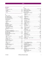
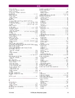
OVERVOLTAGE
auxiliary ................................................................2-9, 5-154
negative sequence ...................................................... 5-152
negative-sequence .......................................................... 2-9
neutral ..................................................................2-8, 5-151
phase ....................................................................2-8, 5-150
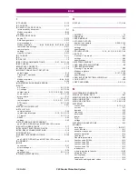
P
PANEL CUTOUT ......................................................... 3-1, 3-2
PARITY ........................................................................... 5-14
PASSWORD SECURITY .................................................... 5-9
PASSWORDS
changing ....................................................................... 4-28
for settings templates ...................................................... 4-5
lost password ................................................. 4-28, 5-9, 5-10
Modbus ........................................................................... B-8
Modbus registers .................................................. B-15, B-19
overview ....................................................................... 1-18
security ........................................................................... 5-8
settings ........................................................................... 5-8
PC SOFTWARE
see entry for ENERVISTA UR SETUP
PERMISSIVE FUNCTIONS ............................................. 5-147
PER-UNIT QUANTITY ........................................................ 5-4
PHASE ANGLE METERING .............................................. 6-13
PHASE CURRENT METERING ......................................... 6-15
PHASE DIRECTIONAL OC
Modbus registers ........................................................... B-33
PHASE DIRECTIONAL OVERCURRENT
FlexLogic™ operands .................................................... 5-89
logic ............................................................................ 5-119
phase A polarization .................................................... 5-117
settings ............................................................. 5-117, 5-118
specifications .................................................................. 2-7
PHASE INSTANTANEOUS OVERCURRENT
PHASE IOC
FlexLogic™ operands .................................................... 5-89
logic ............................................................................ 5-116
Modbus registers ........................................................... B-28
specifications .................................................................. 2-7
PHASE OVERVOLTAGE
FlexLogic™ operands .................................................... 5-89
logic ............................................................................ 5-150
Modbus registers ........................................................... B-33
settings ....................................................................... 5-150
specifications .................................................................. 2-8
PHASE ROTATION .......................................................... 5-67
PHASE TIME OVERCURRENT
PHASE TOC
FlexLogic™ operands .................................................... 5-90
logic ............................................................................ 5-115
Modbus registers ........................................................... B-27
settings ....................................................................... 5-114
specifications .................................................................. 2-7
PHASE UNDERVOLTAGE
FlexLogic™ operands .................................................... 5-90
logic ............................................................................ 5-149
Modbus registers ........................................................... B-32
settings ....................................................................... 5-149
specifications .................................................................. 2-8
PHONE NUMBERS ............................................................ 1-1
POWER METERING
Modbus registers ........................................................... B-13
specifications ................................................................ 2-11
values ........................................................................... 6-17
POWER SUPPLY
description ..................................................................... 3-11
low range ...................................................................... 2-13
specifications ................................................................. 2-13
POWER SYSTEM
Modbus registers .......................................................... B-24
PREFERENCES
Modbus registers .......................................................... B-19
PRODUCT INFORMATION ........................................6-27, B-9
PRODUCT SETUP ............................................................. 5-8
PRODUCTION TESTS ...................................................... 2-17
PROTECTION ELEMENTS ................................................. 5-4
PU QUANTITY ................................................................... 5-4
PUSHBUTTONS, USER-PROGRAMMABLE
see USER-PROGRAMMBLE PUSHBUTTONS
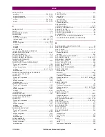
R
RANDOMNESS ALGORITHM FOR HI-Z .............................. 8-2
REACTIVE POWER ................................................. 2-11, 6-17
REAL POWER ......................................................... 2-11, 6-17
REAL TIME CLOCK
Modbus registers .......................................................... B-21
settings ......................................................................... 5-34
REAR TERMINAL ASSIGNMENTS ...................................... 3-7
RECLOSER CURVES ............................................ 5-80, 5-113
REDUNDANT 10BASE-F .................................................. 3-23
RELAY ACTIVATION ........................................................ 4-27
RELAY ARCHITECTURE .................................................. 5-84
RELAY MAINTENANCE ...................................................... 7-2
RELAY NAME .................................................................. 5-64
RELAY NOT PROGRAMMED ............................................ 1-17
REMOTE DEVICES
actual values ................................................................... 6-5
device ID ..................................................................... 5-212
error messages ................................................................ 7-7
FlexLogic™ operands ..................................................... 5-92
Modbus registers ............................... B-11, B-17, B-58, B-59
settings ....................................................................... 5-211
statistics .......................................................................... 6-5
REMOTE INPUTS
actual values ................................................................... 6-3
FlexLogic™ operands ..................................................... 5-92
Modbus registers ........................................ B-11, B-17, B-58
settings ....................................................................... 5-212
specifications ................................................................. 2-13
REMOTE OUTPUTS
DNA-1 bit pair .............................................................. 5-213
Modbus registers .......................................................... B-59
UserSt-1 bit pair .......................................................... 5-213
REPLACEMENT MODULES .................................. 2-4, 2-5, 2-6
RESETTING .......................................................... 5-92, 5-214
REVISION HISTORY ..........................................................F-1
RFI SUSCEPTIBILITY ...................................................... 2-17
RFI, CONDUCTED ........................................................... 2-17
RMS CURRENT ............................................................... 2-11
RMS VOLTAGE ................................................................ 2-11
ROLLING DEMAND .......................................................... 5-42
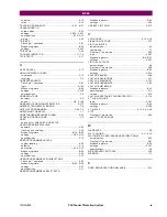
RS232
configuration .................................................................... 1-9
specifications ................................................................. 2-15
wiring ............................................................................ 3-23
RS422
configuration .................................................................. 3-34
timing ............................................................................ 3-35
two-channel application .................................................. 3-34
Summary of Contents for F60 UR Series
Page 2: ......
Page 4: ......
Page 30: ...1 20 F60 Feeder Protection System GE Multilin 1 5 USING THE RELAY 1 GETTING STARTED 1 ...
Page 48: ...2 18 F60 Feeder Protection System GE Multilin 2 2 SPECIFICATIONS 2 PRODUCT DESCRIPTION 2 ...
Page 126: ...4 30 F60 Feeder Protection System GE Multilin 4 2 FACEPLATE INTERFACE 4 HUMAN INTERFACES 4 ...
Page 354: ...5 228 F60 Feeder Protection System GE Multilin 5 9 TESTING 5 SETTINGS 5 ...
Page 382: ...6 28 F60 Feeder Protection System GE Multilin 6 5 PRODUCT INFORMATION 6 ACTUAL VALUES 6 ...
Page 398: ...8 8 F60 Feeder Protection System GE Multilin 8 2 FAULT LOCATOR 8 THEORY OF OPERATION 8 ...
Page 414: ...A 14 F60 Feeder Protection System GE Multilin A 1 PARAMETER LIST APPENDIXA A ...
Page 492: ...B 78 F60 Feeder Protection System GE Multilin B 4 MEMORY MAPPING APPENDIXB B ...
Page 530: ...D 10 F60 Feeder Protection System GE Multilin D 1 IEC 60870 5 104 APPENDIXD D ...
Page 542: ...E 12 F60 Feeder Protection System GE Multilin E 2 DNP POINT LISTS APPENDIXE E ...
Page 558: ...x F60 Feeder Protection System GE Multilin INDEX ...


