


3-6
F60 Feeder Protection System
GE Multilin
3.1 DESCRIPTION
3 HARDWARE
3
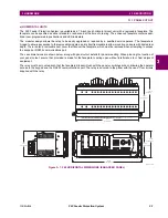
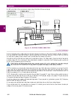
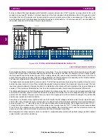
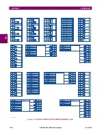
Figure 3–7: UR MODULE WITHDRAWAL AND INSERTION (ENHANCED FACEPLATE)
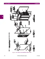
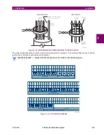
The standard faceplate can be opened to the left, once the sliding latch on the right side has been pushed up, as shown
below. This allows for easy accessibility of the modules for withdrawal.
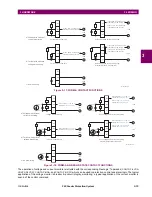
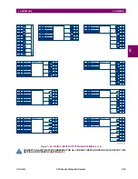
Figure 3–8: UR MODULE WITHDRAWAL AND INSERTION (STANDARD FACEPLATE)
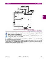
To properly remove a module, the ejector/inserter clips, located at the top and bottom of each module, must be pulled
simultaneously. Before performing this action,
control power must be removed from the relay
. Record the original loca-
tion of the module to ensure that the same or replacement module is inserted into the correct slot. Modules with current
input provide automatic shorting of external CT circuits.
To properly insert a module, ensure that the
correct
module type is inserted into the
correct
slot position. The ejector/
inserter clips located at the top and at the bottom of each module must be in the disengaged position as the module is
smoothly inserted into the slot. Once the clips have cleared the raised edge of the chassis, engage the clips simultaneously.
When the clips have locked into position, the module will be fully inserted.
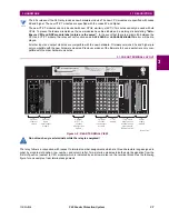
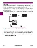
All CPU modules except the 9E are equipped with 10/100Base-T or 100Base-F Ethernet connectors. These con-
nectors must be individually disconnected from the module before it can be removed from the chassis.
842812A1.CDR
NOTE
Summary of Contents for F60 UR Series
Page 2: ......
Page 4: ......
Page 30: ...1 20 F60 Feeder Protection System GE Multilin 1 5 USING THE RELAY 1 GETTING STARTED 1 ...
Page 48: ...2 18 F60 Feeder Protection System GE Multilin 2 2 SPECIFICATIONS 2 PRODUCT DESCRIPTION 2 ...
Page 126: ...4 30 F60 Feeder Protection System GE Multilin 4 2 FACEPLATE INTERFACE 4 HUMAN INTERFACES 4 ...
Page 354: ...5 228 F60 Feeder Protection System GE Multilin 5 9 TESTING 5 SETTINGS 5 ...
Page 382: ...6 28 F60 Feeder Protection System GE Multilin 6 5 PRODUCT INFORMATION 6 ACTUAL VALUES 6 ...
Page 398: ...8 8 F60 Feeder Protection System GE Multilin 8 2 FAULT LOCATOR 8 THEORY OF OPERATION 8 ...
Page 414: ...A 14 F60 Feeder Protection System GE Multilin A 1 PARAMETER LIST APPENDIXA A ...
Page 492: ...B 78 F60 Feeder Protection System GE Multilin B 4 MEMORY MAPPING APPENDIXB B ...
Page 530: ...D 10 F60 Feeder Protection System GE Multilin D 1 IEC 60870 5 104 APPENDIXD D ...
Page 542: ...E 12 F60 Feeder Protection System GE Multilin E 2 DNP POINT LISTS APPENDIXE E ...
Page 558: ...x F60 Feeder Protection System GE Multilin INDEX ...