


3-22
F60 Feeder Protection System
GE Multilin
3.2 WIRING
3 HARDWARE
3
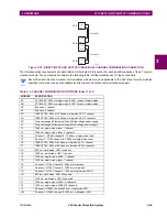
3.2.6 TRANSDUCER INPUTS/OUTPUTS
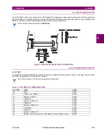
Transducer input modules can receive input signals from external dcmA output transducers (dcmA In) or resistance tem-
perature detectors (RTD). Hardware and software is provided to receive signals from these external transducers and con-
vert these signals into a digital format for use as required.
Transducer output modules provide DC current outputs in several standard dcmA ranges. Software is provided to configure
virtually any analog quantity used in the relay to drive the analog outputs.
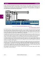
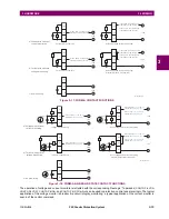
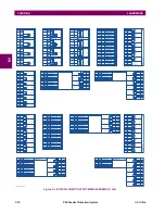
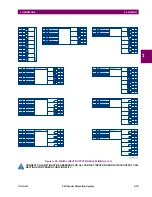
Every transducer input/output module has a total of 24 terminal connections. These connections are arranged as three ter-
minals per row with a total of eight rows. A given row may be used for either inputs or outputs, with terminals in column "a"
having positive polarity and terminals in column "c" having negative polarity. Since an entire row is used for a single input/
output channel, the name of the channel is assigned using the module slot position and row number.
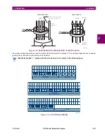
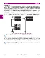
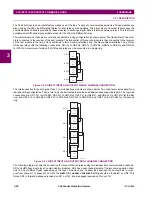
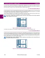
Each module also requires that a connection from an external ground bus be made to terminal 8b. The current outputs
require a twisted-pair shielded cable, where the shield is grounded at one end only. The figure below illustrates the trans-
ducer module types (5A, 5C, 5D, 5E, and 5F) and channel arrangements that may be ordered for the relay.
Wherever a tilde “~” symbol appears, substitute with the slot position of the module.
Figure 3–24: TRANSDUCER INPUT/OUTPUT MODULE WIRING
NOTE
Summary of Contents for F60 UR Series
Page 2: ......
Page 4: ......
Page 30: ...1 20 F60 Feeder Protection System GE Multilin 1 5 USING THE RELAY 1 GETTING STARTED 1 ...
Page 48: ...2 18 F60 Feeder Protection System GE Multilin 2 2 SPECIFICATIONS 2 PRODUCT DESCRIPTION 2 ...
Page 126: ...4 30 F60 Feeder Protection System GE Multilin 4 2 FACEPLATE INTERFACE 4 HUMAN INTERFACES 4 ...
Page 354: ...5 228 F60 Feeder Protection System GE Multilin 5 9 TESTING 5 SETTINGS 5 ...
Page 382: ...6 28 F60 Feeder Protection System GE Multilin 6 5 PRODUCT INFORMATION 6 ACTUAL VALUES 6 ...
Page 398: ...8 8 F60 Feeder Protection System GE Multilin 8 2 FAULT LOCATOR 8 THEORY OF OPERATION 8 ...
Page 414: ...A 14 F60 Feeder Protection System GE Multilin A 1 PARAMETER LIST APPENDIXA A ...
Page 492: ...B 78 F60 Feeder Protection System GE Multilin B 4 MEMORY MAPPING APPENDIXB B ...
Page 530: ...D 10 F60 Feeder Protection System GE Multilin D 1 IEC 60870 5 104 APPENDIXD D ...
Page 542: ...E 12 F60 Feeder Protection System GE Multilin E 2 DNP POINT LISTS APPENDIXE E ...
Page 558: ...x F60 Feeder Protection System GE Multilin INDEX ...


