GE Multilin
F60 Feeder Protection System
6-21
6 ACTUAL VALUES
6.3 METERING
6
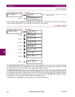
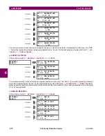
Voltage harmonics are not available on F60 relays configured with the high-impedance fault detection (Hi-Z) fea-
ture.
Voltage harmonics are calculated only for Wye connected phase VTs. Ensure the
SYSTEM SETUP
Ö
AC INPUTS
ÖØ
VOLTAGE BANK F5
ÖØ
PHASE VT XX CONNECTION
setting is “Wye” to enable voltage harmonics metering.
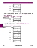
6.3.3 SENSITIVE DIRECTIONAL POWER
PATH: ACTUAL VALUES
ÖØ
METERING
ÖØ
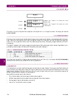
SENSITIVE DIRECTIONAL POWER
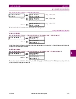
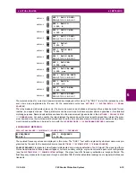
The effective operating quantities of the sensitive directional power elements are displayed here. The display may be useful
to calibrate the feature by compensating the angular errors of the CTs and VTs with the use of the
RCA
and
CALIBRATION
settings.
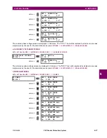
6.3.4 SYNCHROCHECK
PATH: ACTUAL VALUES
ÖØ
METERING
ÖØ
SYNCHROCHECK
Ö
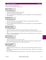
SYNCHROCHECK 1(2)
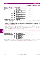
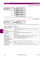
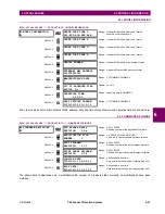
The actual values menu for synchrocheck 2 is identical to that of synchrocheck 1. If a synchrocheck function setting is "Dis-
abled", the corresponding actual values menu item will not be displayed.
6.3.5 TRACKING FREQUENCY
PATH: ACTUAL VALUES
ÖØ
METERING
ÖØ
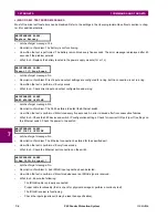
TRACKING FREQUENCY
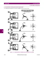
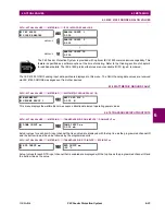
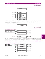
The tracking frequency is displayed here. The frequency is tracked based on the selection of the reference source with the
FREQUENCY AND PHASE REFERENCE
setting in the
SETTINGS
ÖØ
SYSTEM SETUP
ÖØ
POWER SYSTEM
menu. Refer to the
Power System
section of chapter 5 for additional details.
SENSITIVE
DIRECTIONAL POWER
DIRECTIONAL POWER 1
3
Φ
: 0.000 W
MESSAGE
DIRECTIONAL POWER 2
3
Φ
: 0.000 W
SYNCHROCHECK 1
SYNCHROCHECK 1 DELTA
VOLT: 0.000
V
MESSAGE
SYNCHROCHECK 1 DELTA
PHASE: 0.0°
MESSAGE
SYNCHROCHECK 1 DELTA
FREQ: 0.00
Hz
TRACKING FREQUENCY
TRACKING FREQUENCY:
60.00 Hz
NOTE
NOTE
Summary of Contents for F60 UR Series
Page 2: ......
Page 4: ......
Page 30: ...1 20 F60 Feeder Protection System GE Multilin 1 5 USING THE RELAY 1 GETTING STARTED 1 ...
Page 48: ...2 18 F60 Feeder Protection System GE Multilin 2 2 SPECIFICATIONS 2 PRODUCT DESCRIPTION 2 ...
Page 126: ...4 30 F60 Feeder Protection System GE Multilin 4 2 FACEPLATE INTERFACE 4 HUMAN INTERFACES 4 ...
Page 354: ...5 228 F60 Feeder Protection System GE Multilin 5 9 TESTING 5 SETTINGS 5 ...
Page 382: ...6 28 F60 Feeder Protection System GE Multilin 6 5 PRODUCT INFORMATION 6 ACTUAL VALUES 6 ...
Page 398: ...8 8 F60 Feeder Protection System GE Multilin 8 2 FAULT LOCATOR 8 THEORY OF OPERATION 8 ...
Page 414: ...A 14 F60 Feeder Protection System GE Multilin A 1 PARAMETER LIST APPENDIXA A ...
Page 492: ...B 78 F60 Feeder Protection System GE Multilin B 4 MEMORY MAPPING APPENDIXB B ...
Page 530: ...D 10 F60 Feeder Protection System GE Multilin D 1 IEC 60870 5 104 APPENDIXD D ...
Page 542: ...E 12 F60 Feeder Protection System GE Multilin E 2 DNP POINT LISTS APPENDIXE E ...
Page 558: ...x F60 Feeder Protection System GE Multilin INDEX ...


