GE Multilin
F60 Feeder Protection System
3-29
3 HARDWARE
3.3 DIRECT INPUT/OUTPUT COMMUNICATIONS
3
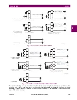
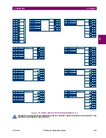
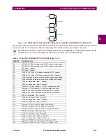
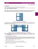
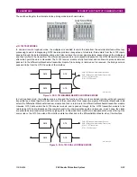
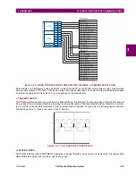
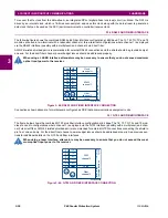
Figure 3–32: DIRECT INPUT AND OUTPUT SINGLE/DUAL CHANNEL COMBINATION CONNECTION
The interconnection requirements are described in further detail in this section for each specific variation of type 7 commu-
nications module. These modules are listed in the following table. All fiber modules use ST type connectors.
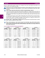
Not all the direct input and output communications modules may be applicable to the F60 relay. Only the modules
specified in the order codes are available as direct input and output communications modules.
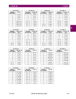
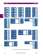
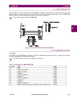
Table 3–4: CHANNEL COMMUNICATION OPTIONS (Sheet 1 of 2)
MODULE
SPECIFICATION
2A
C37.94SM, 1300 nm, single-mode, ELED, 1 channel single-mode
2B
C37.94SM, 1300 nm, single-mode, ELED, 2 channel single-mode
2E
Bi-phase, 1 channel
2F
Bi-phase, 2 channel
2G
IEEE C37.94, 820 nm, 128 kbps, multi-mode, LED, 1 channel
2H
IEEE C37.94, 820 nm, 128 kbps, multi-mode, LED, 2 channels
2S
Six-port managed Ethernet switch with high voltage power supply
2T
Six-port managed Ethernet switch with low voltage power supply
72
1550 nm, single-mode, laser, 1 channel
73
1550 nm, single-mode, laser, 2 channels
74
Channel 1 - RS422; channel 2 - 1550 nm, single-mode, laser
75
Channel 1 - G.703; channel 2 - 1550 nm, single-mode, laser
76
IEEE C37.94, 820 nm, 64 kbps, multi-mode, LED, 1 channel
77
IEEE C37.94, 820 nm, 64 kbps, multi-mode, LED, 2 channels
7A
820 nm, multi-mode, LED, 1 channel
7B
1300 nm, multi-mode, LED, 1 channel
7C
1300 nm, single-mode, ELED, 1 channel
7D
1300 nm, single-mode, laser, 1 channel
7E
Channel 1: G.703, Channel 2: 820 nm, multi-mode
7F
Channel 1: G.703, Channel 2: 1300 nm, multi-mode
7G
Channel 1: G.703, Channel 2: 1300 nm, single-mode ELED
7H
820 nm, multi-mode, LED, 2 channels
7I
1300 nm, multi-mode, LED, 2 channels
7J
1300 nm, single-mode, ELED, 2 channels
7K
1300 nm, single-mode, LASER, 2 channels
7L
Channel 1: RS422, channel: 820 nm, multi-mode, LED
7M
Channel 1: RS422, channel 2: 1300 nm, multi-mode, LED
842013A1.CDR
Tx
Tx
UR #1
Channel #1
Channel #2
UR #2
UR #3
Rx
Rx
Tx1
Tx2
Rx1
Rx2
NOTE
Summary of Contents for F60 UR Series
Page 2: ......
Page 4: ......
Page 30: ...1 20 F60 Feeder Protection System GE Multilin 1 5 USING THE RELAY 1 GETTING STARTED 1 ...
Page 48: ...2 18 F60 Feeder Protection System GE Multilin 2 2 SPECIFICATIONS 2 PRODUCT DESCRIPTION 2 ...
Page 126: ...4 30 F60 Feeder Protection System GE Multilin 4 2 FACEPLATE INTERFACE 4 HUMAN INTERFACES 4 ...
Page 354: ...5 228 F60 Feeder Protection System GE Multilin 5 9 TESTING 5 SETTINGS 5 ...
Page 382: ...6 28 F60 Feeder Protection System GE Multilin 6 5 PRODUCT INFORMATION 6 ACTUAL VALUES 6 ...
Page 398: ...8 8 F60 Feeder Protection System GE Multilin 8 2 FAULT LOCATOR 8 THEORY OF OPERATION 8 ...
Page 414: ...A 14 F60 Feeder Protection System GE Multilin A 1 PARAMETER LIST APPENDIXA A ...
Page 492: ...B 78 F60 Feeder Protection System GE Multilin B 4 MEMORY MAPPING APPENDIXB B ...
Page 530: ...D 10 F60 Feeder Protection System GE Multilin D 1 IEC 60870 5 104 APPENDIXD D ...
Page 542: ...E 12 F60 Feeder Protection System GE Multilin E 2 DNP POINT LISTS APPENDIXE E ...
Page 558: ...x F60 Feeder Protection System GE Multilin INDEX ...

