


GE Multilin
F60 Feeder Protection System
1-5
1 GETTING STARTED
1.3 ENERVISTA UR SETUP SOFTWARE
1
1.3ENERVISTA UR SETUP SOFTWARE
1.3.1 PC REQUIREMENTS
The faceplate keypad and display or the EnerVista UR Setup software interface can be used to communicate with the relay.
The EnerVista UR Setup software interface is the preferred method to edit settings and view actual values because the PC
monitor can display more information in a simple comprehensible format.
The following minimum requirements must be met for the EnerVista UR Setup software to properly operate on a PC.
•
Pentium class or higher processor (Pentium II 300 MHz or higher recommended)
•
Windows 95, 98, 98SE, ME, NT 4.0 (Service Pack 4 or higher), 2000, XP
•
Internet Explorer 4.0 or higher
•
128 MB of RAM (256 MB recommended)
•
200 MB of available space on system drive and 200 MB of available space on installation drive
•
Video capable of displaying 800 x 600 or higher in high-color mode (16-bit color)
•
RS232 and/or Ethernet port for communications to the relay
The following qualified modems have been tested to be compliant with the F60 and the EnerVista UR Setup software.
•
US Robotics external 56K FaxModem 5686
•
US Robotics external Sportster 56K X2
•
PCTEL 2304WT V.92 MDC internal modem
1.3.2 INSTALLATION
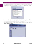
After ensuring the minimum requirements for using EnerVista UR Setup are met (see previous section), use the following
procedure to install the EnerVista UR Setup from the enclosed GE EnerVista CD.
1.
Insert the GE EnerVista CD into your CD-ROM drive.
2.
Click the
Install Now
button and follow the installation instructions to install the no-charge EnerVista software.
3.
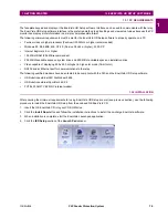
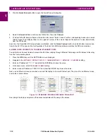
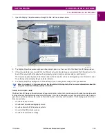
When installation is complete, start the EnerVista Launchpad application.
4.
Click the
IED Setup
section of the
Launch Pad
window.
Summary of Contents for F60 UR Series
Page 2: ......
Page 4: ......
Page 30: ...1 20 F60 Feeder Protection System GE Multilin 1 5 USING THE RELAY 1 GETTING STARTED 1 ...
Page 48: ...2 18 F60 Feeder Protection System GE Multilin 2 2 SPECIFICATIONS 2 PRODUCT DESCRIPTION 2 ...
Page 126: ...4 30 F60 Feeder Protection System GE Multilin 4 2 FACEPLATE INTERFACE 4 HUMAN INTERFACES 4 ...
Page 354: ...5 228 F60 Feeder Protection System GE Multilin 5 9 TESTING 5 SETTINGS 5 ...
Page 382: ...6 28 F60 Feeder Protection System GE Multilin 6 5 PRODUCT INFORMATION 6 ACTUAL VALUES 6 ...
Page 398: ...8 8 F60 Feeder Protection System GE Multilin 8 2 FAULT LOCATOR 8 THEORY OF OPERATION 8 ...
Page 414: ...A 14 F60 Feeder Protection System GE Multilin A 1 PARAMETER LIST APPENDIXA A ...
Page 492: ...B 78 F60 Feeder Protection System GE Multilin B 4 MEMORY MAPPING APPENDIXB B ...
Page 530: ...D 10 F60 Feeder Protection System GE Multilin D 1 IEC 60870 5 104 APPENDIXD D ...
Page 542: ...E 12 F60 Feeder Protection System GE Multilin E 2 DNP POINT LISTS APPENDIXE E ...
Page 558: ...x F60 Feeder Protection System GE Multilin INDEX ...


