5-28
F60 Feeder Protection System
GE Multilin
5.2 PRODUCT SETUP
5 SETTINGS
5
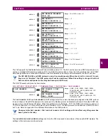
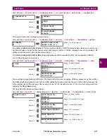
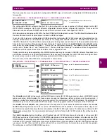
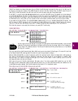
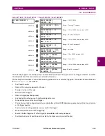
The measured value settings for each of the 32 analog values are shown below.
PATH: SETTINGS
Ö
PRODUCT...
ÖØ
COMMUNICATIONS
ÖØ
IEC 61850...
ÖØ
GGIO4...
Ö
GGIO4 ANALOG 1(32) MEASURED VALUE
These settings are configured as follows.
•
ANALOG IN 1 VALUE
: This setting selects the FlexAnalog value to drive the instantaneous value of each GGIO4 ana-
log status value (GGIO4.MX.AnIn1.instMag.f).
•
ANALOG IN 1 DB
: This setting specifies the deadband for each analog value. Refer to IEC 61850-7-1 and 61850-7-3
for details. The deadband is used to determine when to update the deadbanded magnitude from the instantaneous
magnitude. The deadband is a percentage of the difference between the maximum and minimum values.
•
ANALOG IN 1 MIN
: This setting specifies the minimum value for each analog value. Refer to IEC 61850-7-1 and
61850-7-3 for details. This minimum value is used to determine the deadband. The deadband is used in the determina-
tion of the deadbanded magnitude from the instantaneous magnitude.
•
ANALOG IN 1 MAX
: This setting defines the maximum value for each analog value. Refer to IEC 61850-7-1 and
61850-7-3 for details. This maximum value is used to determine the deadband. The deadband is used in the determi-
nation of the deadbanded magnitude from the instantaneous magnitude.
Note that the
ANALOG IN 1 MIN
and
ANALOG IN 1 MAX
settings are stored as IEEE 754 / IEC 60559 floating point
numbers. Because of the large range of these settings, not all values can be stored. Some values may be rounded
to the closest possible floating point number.
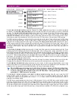
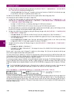
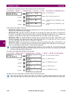
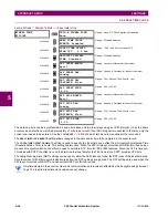
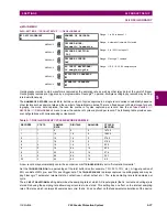
The report control configuration settings are shown below:
PATH: SETTINGS
Ö
PRODUCT SETUP
ÖØ
COMMUNICATIONS
ÖØ
IEC 61850...
ÖØ
REPORT...
Ö
REPORT 1(6) CONFIGURATION
Changes to the report configuration will not take effect until the F60 is restarted.
Please disconnect any IEC 61850 client connection to the F60 prior to making setting changes to the report config-
uration. Disconnecting the rear Ethernet connection from the F60 will disconnect the IEC 61850 client connection.
GGIO4 ANALOG 1
MEASURED VALUE
ANALOG IN 1 VALUE:
Off
Range: any FlexAnalog value
MESSAGE
ANALOG IN 1 DB:
0.000
Range: 0.000 to 100.000 in steps of 0.001
MESSAGE
ANALOG IN 1 MIN:
0.000
Range: –1000000000.000 to 1000000000.000 in steps
of 0.001
MESSAGE
ANALOG IN 1 MAX:
0.000
Range: –1000000000.000 to 1000000000.000 in steps
of 0.001
REPORT 1
CONFIGURATION
REPORT 1
RptID:
Range: up to 66 alphanumeric characters
MESSAGE
REPORT 1
OptFlds:
0
Range: 0 to 65535 in steps of 1
MESSAGE
REPORT 1
BufTm:
0
Range: 0 to 4294967295 in steps of 1
MESSAGE
REPORT 1
TrgOps:
0
Range: 0 to 65535 in steps of 1
MESSAGE
REPORT 1
IntgPd:
0
Range: 0 to 4294967295 in steps of 1
NOTE
NOTE
Summary of Contents for F60 UR Series
Page 2: ......
Page 4: ......
Page 30: ...1 20 F60 Feeder Protection System GE Multilin 1 5 USING THE RELAY 1 GETTING STARTED 1 ...
Page 48: ...2 18 F60 Feeder Protection System GE Multilin 2 2 SPECIFICATIONS 2 PRODUCT DESCRIPTION 2 ...
Page 126: ...4 30 F60 Feeder Protection System GE Multilin 4 2 FACEPLATE INTERFACE 4 HUMAN INTERFACES 4 ...
Page 354: ...5 228 F60 Feeder Protection System GE Multilin 5 9 TESTING 5 SETTINGS 5 ...
Page 382: ...6 28 F60 Feeder Protection System GE Multilin 6 5 PRODUCT INFORMATION 6 ACTUAL VALUES 6 ...
Page 398: ...8 8 F60 Feeder Protection System GE Multilin 8 2 FAULT LOCATOR 8 THEORY OF OPERATION 8 ...
Page 414: ...A 14 F60 Feeder Protection System GE Multilin A 1 PARAMETER LIST APPENDIXA A ...
Page 492: ...B 78 F60 Feeder Protection System GE Multilin B 4 MEMORY MAPPING APPENDIXB B ...
Page 530: ...D 10 F60 Feeder Protection System GE Multilin D 1 IEC 60870 5 104 APPENDIXD D ...
Page 542: ...E 12 F60 Feeder Protection System GE Multilin E 2 DNP POINT LISTS APPENDIXE E ...
Page 558: ...x F60 Feeder Protection System GE Multilin INDEX ...

