GE Multilin
F60 Feeder Protection System
5-13
5 SETTINGS
5.2 PRODUCT SETUP
5
5.2.3 CLEAR RELAY RECORDS
PATH: SETTINGS
Ö
PRODUCT SETUP
ÖØ
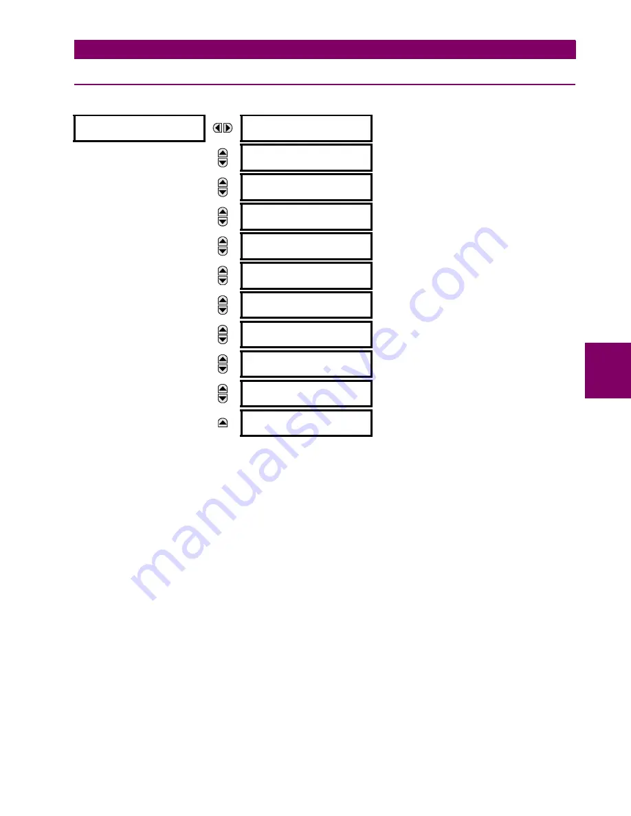
CLEAR RELAY RECORDS
Selected records can be cleared from user-programmable conditions with FlexLogic™ operands. Assigning user-program-
mable pushbuttons to clear specific records are typical applications for these commands. Since the F60 responds to rising
edges of the configured FlexLogic™ operands, they must be asserted for at least 50 ms to take effect.
Clearing records with user-programmable operands is not protected by the command password. However, user-program-
mable pushbuttons are protected by the command password. Thus, if they are used to clear records, the user-programma-
ble pushbuttons can provide extra security if required.
For example, to assign User-Programmable Pushbutton 1 to clear demand records, the following settings should be
applied.
1.
Assign the clear demand function to Pushbutton 1 by making the following change in the
SETTINGS
Ö
PRODUCT SETUP
ÖØ
CLEAR RELAY RECORDS
menu:
CLEAR DEMAND:
“
PUSHBUTTON 1 ON
”
2.
Set the properties for User-Programmable Pushbutton 1 by making the following changes in the
SETTINGS
Ö
PRODUCT
SETUP
ÖØ
USER-PROGRAMMABLE PUSHBUTTONS
Ö
USER PUSHBUTTON 1
menu:
PUSHBUTTON 1 FUNCTION:
“Self-reset”
PUSHBTN 1 DROP-OUT TIME:
“0.20 s”
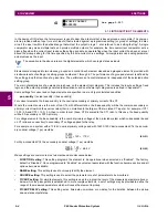
CLEAR RELAY
RECORDS
CLEAR FAULT REPORTS:
Off
Range: FlexLogic™ operand
MESSAGE
CLEAR EVENT RECORDS:
Off
Range: FlexLogic™ operand
MESSAGE
CLEAR OSCILLOGRAPHY?
No
Range: FlexLogic™ operand
MESSAGE
CLEAR DATA LOGGER:
Off
Range: FlexLogic™ operand
MESSAGE
CLEAR ARC AMPS 1:
Off
Range: FlexLogic™ operand
MESSAGE
CLEAR ARC AMPS 2:
Off
Range: FlexLogic™ operand
MESSAGE
CLEAR DEMAND:
Off
Range: FlexLogic™ operand
MESSAGE
CLEAR ENERGY:
Off
Range: FlexLogic™ operand
MESSAG
CLEAR HIZ RECORDS:
Off
Range: FlexLogic™ operand
MESSAGE
RESET UNAUTH ACCESS:
Off
Range: FlexLogic™ operand
MESSAGE
CLEAR DIR I/O STATS:
Off
Range: FlexLogic™ operand.
Valid only for units with Direct I/O module.
Summary of Contents for F60 UR Series
Page 2: ......
Page 4: ......
Page 30: ...1 20 F60 Feeder Protection System GE Multilin 1 5 USING THE RELAY 1 GETTING STARTED 1 ...
Page 48: ...2 18 F60 Feeder Protection System GE Multilin 2 2 SPECIFICATIONS 2 PRODUCT DESCRIPTION 2 ...
Page 126: ...4 30 F60 Feeder Protection System GE Multilin 4 2 FACEPLATE INTERFACE 4 HUMAN INTERFACES 4 ...
Page 354: ...5 228 F60 Feeder Protection System GE Multilin 5 9 TESTING 5 SETTINGS 5 ...
Page 382: ...6 28 F60 Feeder Protection System GE Multilin 6 5 PRODUCT INFORMATION 6 ACTUAL VALUES 6 ...
Page 398: ...8 8 F60 Feeder Protection System GE Multilin 8 2 FAULT LOCATOR 8 THEORY OF OPERATION 8 ...
Page 414: ...A 14 F60 Feeder Protection System GE Multilin A 1 PARAMETER LIST APPENDIXA A ...
Page 492: ...B 78 F60 Feeder Protection System GE Multilin B 4 MEMORY MAPPING APPENDIXB B ...
Page 530: ...D 10 F60 Feeder Protection System GE Multilin D 1 IEC 60870 5 104 APPENDIXD D ...
Page 542: ...E 12 F60 Feeder Protection System GE Multilin E 2 DNP POINT LISTS APPENDIXE E ...
Page 558: ...x F60 Feeder Protection System GE Multilin INDEX ...


