


GE Multilin
F60 Feeder Protection System
5-149
5 SETTINGS
5.5 GROUPED ELEMENTS
5
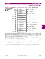
b) PHASE UNDERVOLTAGE
(ANSI 27P)
PATH: SETTINGS
ÖØ
GROUPED ELEMENTS
Ö
SETTING GROUP 1(6)
ÖØ
VOLTAGE ELEMENTS
Ö
PHASE UNDERVOLTAGE1(2)
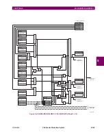
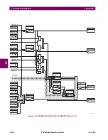
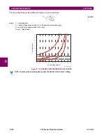
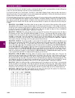
This element may be used to give a desired time-delay operating characteristic versus the applied fundamental voltage
(phase-to-ground or phase-to-phase for wye VT connection, or phase-to-phase for delta VT connection) or as a definite
time element. The element resets instantaneously if the applied voltage exceeds the dropout voltage. The delay setting
selects the minimum operating time of the phase undervoltage. The minimum voltage setting selects the operating voltage
below which the element is blocked (a setting of “0” will allow a dead source to be considered a fault condition).
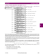
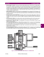
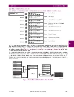
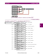
Figure 5–73: PHASE UNDERVOLTAGE1 SCHEME LOGIC
PHASE
UNDERVOLTAGE1
PHASE UV1
FUNCTION: Disabled
Range: Disabled, Enabled
MESSAGE
PHASE UV1 SIGNAL
SOURCE: SRC 1
Range: SRC 1, SRC 2
MESSAGE
PHASE UV1 MODE:
Phase to Ground
Range: Phase to Ground, Phase to Phase
MESSAGE
PHASE UV1
PICKUP: 1.000 pu
Range: 0.000 to 3.000 pu in steps of 0.001
MESSAGE
PHASE UV1
CURVE: Definite Time
Range: Definite Time, Inverse Time
MESSAGE
PHASE UV1
DELAY: 1.00
s
Range: 0.00 to 600.00 s in steps of 0.01
MESSAGE
PHASE UV1 MINIMUM
VOLTAGE: 0.100 pu
Range: 0.000 to 3.000 pu in steps of 0.001
MESSAGE
PHASE UV1 BLOCK:
Off
Range: FlexLogic™ operand
MESSAGE
PHASE UV1
TARGET: Self-reset
Range: Self-reset, Latched, Disabled
MESSAGE
PHASE UV1
EVENTS: Disabled
Range: Disabled, Enabled
PHASE UV1
FUNCTION:
PHASE UV1
BLOCK:
PHASE UV1 SOURCE:
PHASE UV1 MODE:
PHASE UV1
PICKUP:
PHASE UV1
CURVE:
PHASE UV1
DELAY:
PHASE UV1
MINIMUM VOLTAGE:
Disabled = 0
Off = 0
Source VT = Delta
Phase to Ground Phase to Phase
RUN
RUN
VCG or VCA PICKUP
VBG or VBC PICKUP
VAG or VAB Minimum
VBG or VBC Minimum
VCG or VCA Minimum
Source VT = Wye
VAG
VAB
VBG
VBC
VCG
VCA
Enabled = 1
VAB
VBC
VCA
PHASE UV1 A PKP
PHASE UV1 B PKP
PHASE UV1 C PKP
PHASE UV1 PKP
PHASE UV1 A DPO
PHASE UV1 B DPO
PHASE UV1 C DPO
PHASE UV1 A OP
PHASE UV1 B OP
PHASE UV1 C OP
PHASE UV1 OP
AND
SETTING
SETTING
SETTING
SETTING
SETTING
SETTING
FLEXLOGIC OPERANDS
FLEXLOGIC OPERAND
FLEXLOGIC OPERAND
827039AB.CDR
AND
AND
AND
OR
OR
<
<
<
<
<
}
t
V
t
t
V
V
VAG or VAB PICKUP
<
RUN
PHASE UV1 DPO
FLEXLOGIC OPERAND
AND
Summary of Contents for F60 UR Series
Page 2: ......
Page 4: ......
Page 30: ...1 20 F60 Feeder Protection System GE Multilin 1 5 USING THE RELAY 1 GETTING STARTED 1 ...
Page 48: ...2 18 F60 Feeder Protection System GE Multilin 2 2 SPECIFICATIONS 2 PRODUCT DESCRIPTION 2 ...
Page 126: ...4 30 F60 Feeder Protection System GE Multilin 4 2 FACEPLATE INTERFACE 4 HUMAN INTERFACES 4 ...
Page 354: ...5 228 F60 Feeder Protection System GE Multilin 5 9 TESTING 5 SETTINGS 5 ...
Page 382: ...6 28 F60 Feeder Protection System GE Multilin 6 5 PRODUCT INFORMATION 6 ACTUAL VALUES 6 ...
Page 398: ...8 8 F60 Feeder Protection System GE Multilin 8 2 FAULT LOCATOR 8 THEORY OF OPERATION 8 ...
Page 414: ...A 14 F60 Feeder Protection System GE Multilin A 1 PARAMETER LIST APPENDIXA A ...
Page 492: ...B 78 F60 Feeder Protection System GE Multilin B 4 MEMORY MAPPING APPENDIXB B ...
Page 530: ...D 10 F60 Feeder Protection System GE Multilin D 1 IEC 60870 5 104 APPENDIXD D ...
Page 542: ...E 12 F60 Feeder Protection System GE Multilin E 2 DNP POINT LISTS APPENDIXE E ...
Page 558: ...x F60 Feeder Protection System GE Multilin INDEX ...


