


5-152
F60 Feeder Protection System
GE Multilin
5.5 GROUPED ELEMENTS
5 SETTINGS
5
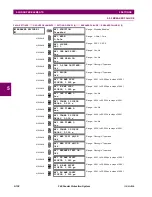
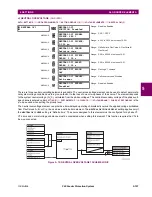
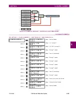
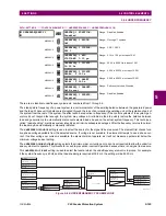
e) NEGATIVE SEQUENCE OVERVOLTAGE
(ANSI 59_2)
PATH: SETTINGS
ÖØ
GROUPED ELEMENTS
Ö
SETTING GROUP 1(6)
ÖØ
VOLTAGE ELEMENTS
ÖØ
NEG SEQ OV1(3)
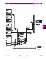
There are three negative-sequence overvoltage elements available.
The negative-sequence overvoltage element may be used to detect loss of one or two phases of the source, a reversed
phase sequence of voltage, or a non-symmetrical system voltage condition.
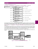
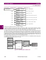
Figure 5–76: NEGATIVE-SEQUENCE OVERVOLTAGE SCHEME LOGIC
NEG SEQ OV1
NEG SEQ OV1
FUNCTION: Disabled
Range: Disabled, Enabled
MESSAGE
NEG SEQ OV1 SIGNAL
SOURCE: SRC 1
Range: SRC 1, SRC 2
MESSAGE
NEG SEQ OV1 PICKUP:
0.300 pu
Range: 0.000 to 1.250 pu in steps of 0.001
MESSAGE
NEG SEQ OV1 PICKUP
DELAY: 0.50
s
Range: 0.00 to 600.00 s in steps of 0.01
MESSAGE
NEG SEQ OV1 RESET
DELAY: 0.50
s
Range: 0.00 to 600.00 s in steps of 0.01
MESSAGE
NEG SEQ OV1 BLOCK:
Off
Range: FlexLogic™ operand
MESSAGE
NEG SEQ OV1 TARGET:
Self-reset
Range: Self-reset, Latched, Disabled
MESSAGE
NEG SEQ OV1 EVENTS:
Disabled
Range: Disabled, Enabled
SETTING
SETTINGS
FLEXLOGIC OPERANDS
SETTING
SETTING
NEG SEQ OV1
FUNCTION:
NEG SEQ OV1 RESET
DELAY:
NEG SEQ OV1 PICKUP
DELAY:
NEG SEQ OV1 PKP
NEG SEQ OV1 DPO
NEG SEQ OV1 OP
NEG SEQ OV1 BLOCK:
Disabled = 0
Off = 0
Enabled = 1
NEG SEQ OV1 SIGNAL
SOURCE:
Wye VT
Delta VT
V_2
827839A3.CDR
AND
SETTING
NEG SEQ OV1 PICKUP:
V_2 or 3 × V_2
PKP
≥
RUN
t
t
PKP
RST
3 × V_2
Summary of Contents for F60 UR Series
Page 2: ......
Page 4: ......
Page 30: ...1 20 F60 Feeder Protection System GE Multilin 1 5 USING THE RELAY 1 GETTING STARTED 1 ...
Page 48: ...2 18 F60 Feeder Protection System GE Multilin 2 2 SPECIFICATIONS 2 PRODUCT DESCRIPTION 2 ...
Page 126: ...4 30 F60 Feeder Protection System GE Multilin 4 2 FACEPLATE INTERFACE 4 HUMAN INTERFACES 4 ...
Page 354: ...5 228 F60 Feeder Protection System GE Multilin 5 9 TESTING 5 SETTINGS 5 ...
Page 382: ...6 28 F60 Feeder Protection System GE Multilin 6 5 PRODUCT INFORMATION 6 ACTUAL VALUES 6 ...
Page 398: ...8 8 F60 Feeder Protection System GE Multilin 8 2 FAULT LOCATOR 8 THEORY OF OPERATION 8 ...
Page 414: ...A 14 F60 Feeder Protection System GE Multilin A 1 PARAMETER LIST APPENDIXA A ...
Page 492: ...B 78 F60 Feeder Protection System GE Multilin B 4 MEMORY MAPPING APPENDIXB B ...
Page 530: ...D 10 F60 Feeder Protection System GE Multilin D 1 IEC 60870 5 104 APPENDIXD D ...
Page 542: ...E 12 F60 Feeder Protection System GE Multilin E 2 DNP POINT LISTS APPENDIXE E ...
Page 558: ...x F60 Feeder Protection System GE Multilin INDEX ...


