


GE Multilin
F60 Feeder Protection System
2-5
2 PRODUCT DESCRIPTION
2.1 INTRODUCTION
2
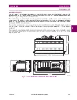
Not all replacement modules may be applicable to the F60 relay. Only the modules specified in the order codes are
available as replacement modules.
Replacement module codes are subject to change without notice. Refer to the GE Multilin ordering page at
www.GEindustrial.com/multilin/order.htm
for the latest details concerning F60 ordering options.
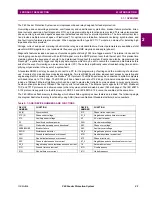
The replacement module order codes for the horizontal mount units are shown below.
Table 2–5: ORDER CODES FOR REPLACEMENT MODULES, HORIZONTAL UNITS
UR
-
**
-
*
POWER SUPPLY
(redundant supply only available in horizontal units;
must be same type as main supply)
|
1H
|
125 / 250 V AC/DC
|
1L
|
24 to 48 V (DC only)
|
RH
|
redundant 125 / 250 V AC/DC
|
RH
|
redundant 24 to 48 V (DC only)
CPU
|
9E
|
RS485 and RS485 (Modbus RTU, DNP 3.0)
|
9G
|
RS485 and 10Base-F (Ethernet, Modbus TCP/IP, DNP 3.0)
|
9H
|
RS485 and Redundant 10Base-F (Ethernet, Modbus TCP/IP, DNP 3.0)
|
9J
|
RS485 and multi-mode ST 100Base-FX (Ethernet, Modbus TCP/IP, DNP 3.0)
|
9K
|
RS485 and multi-mode ST redundant 100Base-FX (Ethernet, Modbus TCP/IP, DNP 3.0)
|
9L
|
RS485 and single mode SC 100Base-FX (Ethernet, Modbus TCP/IP, DNP 3.0)
|
9M
|
RS485 and single mode SC redundant 100Base-FX (Ethernet, Modbus TCP/IP, DNP 3.0)
|
9N
|
RS485 and 10/100Base-T (Ethernet, Modbus TCP/IP, DNP 3.0)
|
9P
|
RS485 and single mode ST 100Base-FX (Ethernet, Modbus TCP/IP, DNP 3.0)
|
9R
|
RS485 and single mode ST redundant 100Base-FX (Ethernet, Modbus TCP/IP, DNP 3.0)
|
9S
|
RS485 and six-port managed Ethernet switch
FACEPLATE/DISPLAY
|
3C
|
Horizontal faceplate with keypad and English display
|
3D
|
Horizontal faceplate with keypad and French display
|
3R
|
Horizontal faceplate with keypad and Russian display
|
3A
|
Horizontal faceplate with keypad and Chinese display
|
3P
|
Horizontal faceplate with keypad, user-programmable pushbuttons, and English display
|
3G
|
Horizontal faceplate with keypad, user-programmable pushbuttons, and French display
|
3S
|
Horizontal faceplate with keypad, user-programmable pushbuttons, and Russian display
|
3B
|
Horizontal faceplate with keypad, user-programmable pushbuttons, and Chinese display
|
3K
|
Enhanced front panel with English display
|
3M
|
Enhanced front panel with French display
|
3Q
|
Enhanced front panel with Russian display
|
3U
|
Enhanced front panel with Chinese display
|
3L
|
Enhanced front panel with English display and user-programmable pushbuttons
|
3N
|
Enhanced front panel with French display and user-programmable pushbuttons
|
3T
|
Enhanced front panel with Russian display and user-programmable pushbuttons
|
3V
|
Enhanced front panel with Chinese display and user-programmable pushbuttons
DIGITAL INPUTS AND OUTPUTS
|
4A
|
4 Solid-State (no monitoring) MOSFET outputs
|
4B
|
4 Solid-State (voltage with optional current) MOSFET outputs
|
4C
|
4 Solid-State (current with optional voltage) MOSFET outputs
|
4D
|
16 digital inputs with Auto-Burnishing
|
4L
|
14 Form-A (no monitoring) Latching outputs
|
67
|
8 Form-A (no monitoring) outputs
|
6A
|
2 Form-A (voltage with optional current) and 2 Form-C outputs, 8 digital inputs
|
6B
|
2 Form-A (voltage with optional current) and 4 Form-C outputs, 4 digital inputs
|
6C
|
8 Form-C outputs
|
6D
|
16 digital inputs
|
6E
|
4 Form-C outputs, 8 digital inputs
|
6F
|
8 Fast Form-C outputs
|
6G
|
4 Form-A (voltage with optional current) outputs, 8 digital inputs
|
6H
|
6 Form-A (voltage with optional current) outputs, 4 digital inputs
|
6K
|
4 Form-C and 4 Fast Form-C outputs
|
6L
|
2 Form-A (current with optional voltage) and 2 Form-C outputs, 8 digital inputs
|
6M
|
2 Form-A (current with optional voltage) and 4 Form-C outputs, 4 digital inputs
|
6N
|
4 Form-A (current with optional voltage) outputs, 8 digital inputs
|
6P
|
6 Form-A (current with optional voltage) outputs, 4 digital inputs
|
6R
|
2 Form-A (no monitoring) and 2 Form-C outputs, 8 digital inputs
|
6S
|
2 Form-A (no monitoring) and 4 Form-C outputs, 4 digital inputs
|
6T
|
4 Form-A (no monitoring) outputs, 8 digital inputs
|
6U
|
6 Form-A (no monitoring) outputs, 4 digital inputs
CT/VT
MODULES
(NOT AVAILABLE FOR THE C30)
|
8F
|
Standard 4CT/4VT
|
8G
|
Sensitive Ground 4CT/4VT
|
8H
|
Standard 8CT
|
8J
|
Sensitive Ground 8CT
|
8L
|
Standard 4CT/4VT with enhanced diagnostics
|
8M
|
Sensitive Ground 4CT/4VT with enhanced diagnostics
|
8N
|
Standard 8CT with enhanced diagnostics
|
8R
|
Sensitive Ground 8CT with enhanced diagnostics
|
8Z
|
HI-Z 4CT
INTER-RELAY COMMUNICATIONS
|
2A
|
C37.94SM, 1300nm single-mode, ELED, 1 channel single-mode
|
2B
|
C37.94SM, 1300nm single-mode, ELED, 2 channel single-mode
|
2E
|
Bi-phase, single channel
|
2F
|
Bi-phase, dual channel
|
2G
|
IEEE C37.94, 820 nm, 64 kbps, multimode, LED, 1 Channel
|
2H
|
IEEE C37.94, 820 nm, 64 kbps, multimode, LED, 2 Channels
|
2S
|
Six-port managed Ethernet switch with high voltage power supply (110 to 250 V DC / 100 to 240 V AC)
|
2T
|
Six-port managed Ethernet switch with low voltage power supply (48 V DC)
|
72
|
1550 nm, single-mode, LASER, 1 Channel
|
73
|
1550 nm, single-mode, LASER, 2 Channel
|
74
|
Channel 1 - RS422; Channel 2 - 1550 nm, single-mode, LASER
|
75
|
Channel 1 - G.703; Channel 2 - 1550 nm, Single-mode LASER
|
76
|
IEEE C37.94, 820 nm, multimode, LED, 1 Channel
|
77
|
IEEE C37.94, 820 nm, multimode, LED, 2 Channels
|
7A
|
820 nm, multi-mode, LED, 1 Channel
|
7B
|
1300 nm, multi-mode, LED, 1 Channel
|
7C
|
1300 nm, single-mode, ELED, 1 Channel
|
7D
|
1300 nm, single-mode, LASER, 1 Channel
|
7E
|
Channel 1 - G.703; Channel 2 - 820 nm, multi-mode
|
7F
|
Channel 1 - G.703; Channel 2 - 1300 nm, multi-mode
|
7G
|
Channel 1 - G.703; Channel 2 - 1300 nm, single-mode ELED
|
7H
|
820 nm, multi-mode, LED, 2 Channels
|
7I
|
1300 nm, multi-mode, LED, 2 Channels
|
7J
|
1300 nm, single-mode, ELED, 2 Channels
|
7K
|
1300 nm, single-mode, LASER, 2 Channels
|
7L
|
Channel 1 - RS422; Channel 2 - 820 nm, multi-mode, LED
|
7M
|
Channel 1 - RS422; Channel 2 - 1300 nm, multi-mode, LED
|
7N
|
Channel 1 - RS422; Channel 2 - 1300 nm, single-mode, ELED
|
7P
|
Channel 1 - RS422; Channel 2 - 1300 nm, single-mode, LASER
|
7Q
|
Channel 1 - G.703; Channel 2 - 1300 nm, single-mode LASER
|
7R
|
G.703, 1 Channel
|
7S
|
G.703, 2 Channels
|
7T
|
RS422, 1 Channel
|
7W
|
RS422, 2 Channels
TRANSDUCER
INPUTS/OUTPUTS
|
5A
|
4 dcmA inputs, 4 dcmA outputs (only one 5A module is allowed)
|
5C
|
8 RTD inputs
|
5D
|
4 RTD inputs, 4 dcmA outputs (only one 5D module is allowed)
|
5E
|
4 dcmA inputs, 4 RTD inputs
|
5F
|
8 dcmA inputs
NOTE
NOTE
Summary of Contents for F60 UR Series
Page 2: ......
Page 4: ......
Page 30: ...1 20 F60 Feeder Protection System GE Multilin 1 5 USING THE RELAY 1 GETTING STARTED 1 ...
Page 48: ...2 18 F60 Feeder Protection System GE Multilin 2 2 SPECIFICATIONS 2 PRODUCT DESCRIPTION 2 ...
Page 126: ...4 30 F60 Feeder Protection System GE Multilin 4 2 FACEPLATE INTERFACE 4 HUMAN INTERFACES 4 ...
Page 354: ...5 228 F60 Feeder Protection System GE Multilin 5 9 TESTING 5 SETTINGS 5 ...
Page 382: ...6 28 F60 Feeder Protection System GE Multilin 6 5 PRODUCT INFORMATION 6 ACTUAL VALUES 6 ...
Page 398: ...8 8 F60 Feeder Protection System GE Multilin 8 2 FAULT LOCATOR 8 THEORY OF OPERATION 8 ...
Page 414: ...A 14 F60 Feeder Protection System GE Multilin A 1 PARAMETER LIST APPENDIXA A ...
Page 492: ...B 78 F60 Feeder Protection System GE Multilin B 4 MEMORY MAPPING APPENDIXB B ...
Page 530: ...D 10 F60 Feeder Protection System GE Multilin D 1 IEC 60870 5 104 APPENDIXD D ...
Page 542: ...E 12 F60 Feeder Protection System GE Multilin E 2 DNP POINT LISTS APPENDIXE E ...
Page 558: ...x F60 Feeder Protection System GE Multilin INDEX ...