B-32
F60 Feeder Protection System
GE Multilin
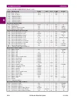
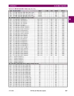
B.4 MEMORY MAPPING
APPENDIX B
B
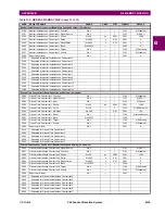
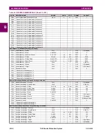
64A4
Negative Sequence Overvoltage Reset Delay
0 to 600
s
0.01
F001
50
64A5
Negative Sequence Overvoltage Block
0 to 65535
---
1
F300
0
64A6
Negative Sequence Overvoltage Target
0 to 2
---
1
F109
0 (Self-reset)
64A7
Negative Sequence Overvoltage Events
0 to 1
---
1
F102
0 (Disabled)
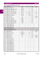
Overfrequency (Read/Write Setting) (4 modules)
64D0
Overfrequency 1 Function
0 to 1
---
1
F102
0 (Disabled)
64D1
Overfrequency 1 Block
0 to 65535
---
1
F300
0
64D2
Overfrequency 1 Source
0 to 5
---
1
F167
0 (SRC 1)
64D3
Overfrequency 1 Pickup
20 to 65
Hz
0.01
F001
6050
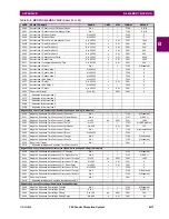
64D4
Overfrequency 1 Pickup Delay
0 to 65.535
s
0.001
F001
500
64D5
Overfrequency 1 Reset Delay
0 to 65.535
s
0.001
F001
500
64D6
Overfrequency 1 Target
0 to 2
---
1
F109
0 (Self-reset)
64D7
Overfrequency 1 Events
0 to 1
---
1
F102
0 (Disabled)
64D8
Reserved (4 items)
0 to 1
---
1
F001
0
64DC
...Repeated for Overfrequency 2
64E8
...Repeated for Overfrequency 3
64F4
...Repeated for Overfrequency 4
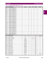
Sensitive Directional Power (Read/Write Grouped Setting) (2 modules)
66A0
Sensitive Directional Power 1 Function
0 to 1
---
1
F102
0 (Disabled)
66A1
Sensitive Directional Power 1 Signal Source
0 to 5
---
1
F167
0 (SRC 1)
66A2
Sensitive Directional Power 1 RCA
0 to 359
degrees
1
F001
0
66A3
Sensitive Directional Power 1 Calibration
0 to 0.95
degrees
0.05
F001
0
66A4
Sensitive Directional Power 1 STG1 SMIN
-1.2 to 1.2
pu
0.001
F002
100
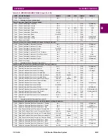
66A5
Sensitive Directional Power 1 STG1 Delay
0 to 600
s
0.01
F001
50
66A6
Sensitive Directional Power 1 STG2 SMIN
-1.2 to 1.2
pu
0.001
F002
100
66A7
Sensitive Directional Power 1 STG2 Delay
0 to 600
s
0.01
F001
2000
66A8
Sensitive Directional Power 1 Block
---
---
---
F001
0
66A9
Sensitive Directional Power 1 Target
0 to 2
---
1
F109
0 (Self-reset)
66AA
Sensitive Directional Power 1 Events
0 to 1
---
1
F102
0 (Disabled)
66AB
Reserved (5 items)
0 to 65535
---
1
F001
0
66B0
...Repeated for Sensitive Directional Power 2
Load Encroachment (Read/Write Grouped Setting)
6700
Load Encroachment Function
0 to 1
---
1
F102
0 (Disabled)
6701
Load Encroachment Source
0 to 5
---
1
F167
0 (SRC 1)
6702
Load Encroachment Minimum Voltage
0 to 3
pu
0.001
F001
250
6703
Load Encroachment Reach
0.02 to 250
ohms
0.01
F001
100
6704
Load Encroachment Angle
5 to 50
degrees
1
F001
30
6705
Load Encroachment Pickup Delay
0 to 65.535
s
0.001
F001
0
6706
Load Encroachment Reset Delay
0 to 65.535
s
0.001
F001
0
6707
Load Encroachment Block
0 to 65535
---
1
F300
0
6708
Load Encroachment Target
0 to 2
---
1
F109
0 (Self-reset)
6709
Load Encroachment Events
0 to 1
---
1
F102
0 (Disabled)
670A
Reserved (6 items)
0 to 65535
---
1
F001
0
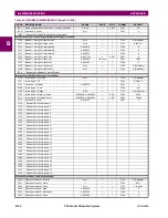
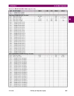
Phase Undervoltage (Read/Write Grouped Setting) (2 modules)
7000
Phase Undervoltage 1 Function
0 to 1
---
1
F102
0 (Disabled)
7001
Phase Undervoltage 1 Signal Source
0 to 5
---
1
F167
0 (SRC 1)
7002
Phase Undervoltage 1 Pickup
0 to 3
pu
0.001
F001
1000
7003
Phase Undervoltage 1 Curve
0 to 1
---
1
F111
0 (Definite Time)
7004
Phase Undervoltage 1 Delay
0 to 600
s
0.01
F001
100
7005
Phase Undervoltage 1 Minimum Voltage
0 to 3
pu
0.001
F001
100
7006
Phase Undervoltage 1 Block
0 to 65535
---
1
F300
0
7007
Phase Undervoltage 1 Target
0 to 2
---
1
F109
0 (Self-reset)
7008
Phase Undervoltage 1 Events
0 to 1
---
1
F102
0 (Disabled)
7009
Phase Undervoltage 1 Measurement Mode
0 to 1
---
1
F186
0 (Phase to Ground)
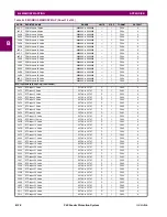
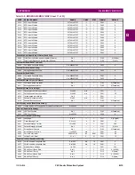
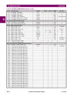
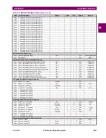
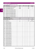
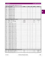
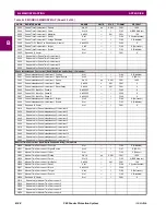
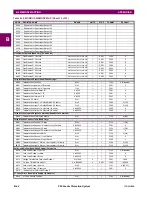
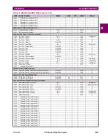
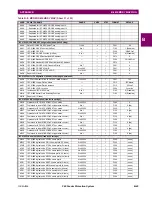
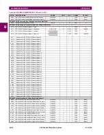
Table B–9: MODBUS MEMORY MAP (Sheet 24 of 53)
ADDR
REGISTER NAME
RANGE
UNITS
STEP
FORMAT
DEFAULT
Summary of Contents for F60 UR Series
Page 2: ......
Page 4: ......
Page 30: ...1 20 F60 Feeder Protection System GE Multilin 1 5 USING THE RELAY 1 GETTING STARTED 1 ...
Page 48: ...2 18 F60 Feeder Protection System GE Multilin 2 2 SPECIFICATIONS 2 PRODUCT DESCRIPTION 2 ...
Page 126: ...4 30 F60 Feeder Protection System GE Multilin 4 2 FACEPLATE INTERFACE 4 HUMAN INTERFACES 4 ...
Page 354: ...5 228 F60 Feeder Protection System GE Multilin 5 9 TESTING 5 SETTINGS 5 ...
Page 382: ...6 28 F60 Feeder Protection System GE Multilin 6 5 PRODUCT INFORMATION 6 ACTUAL VALUES 6 ...
Page 398: ...8 8 F60 Feeder Protection System GE Multilin 8 2 FAULT LOCATOR 8 THEORY OF OPERATION 8 ...
Page 414: ...A 14 F60 Feeder Protection System GE Multilin A 1 PARAMETER LIST APPENDIXA A ...
Page 492: ...B 78 F60 Feeder Protection System GE Multilin B 4 MEMORY MAPPING APPENDIXB B ...
Page 530: ...D 10 F60 Feeder Protection System GE Multilin D 1 IEC 60870 5 104 APPENDIXD D ...
Page 542: ...E 12 F60 Feeder Protection System GE Multilin E 2 DNP POINT LISTS APPENDIXE E ...
Page 558: ...x F60 Feeder Protection System GE Multilin INDEX ...

