


2-4
F60 Feeder Protection System
GE Multilin
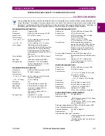
2.1 INTRODUCTION
2 PRODUCT DESCRIPTION
2
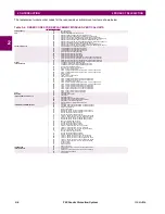
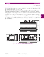
The order codes for the reduced size vertical mount units are shown below.
2.1.3 REPLACEMENT MODULES
Replacement modules can be ordered separately as shown below. When ordering a replacement CPU module or face-
plate, please provide the serial number of your existing unit.
Table 2–4: F60 ORDER CODES (REDUCED SIZE VERTICAL UNITS)
F60
-
*
**
-
*
*
*
- F
**
- H
**
- M
**
-
P/R
**
Reduced Size Vertical Mount (see note regarding P/R slot below)
BASE UNIT
F60
|
|
|
|
|
|
|
|
|
Base Unit
CPU
E
|
|
|
|
|
|
|
|
RS485 and RS485
G
|
|
|
|
|
|
|
|
RS485 and multi-mode ST 10Base-F
H
|
|
|
|
|
|
|
|
RS485 and multi-mode ST redundant 10Base-F
J
|
|
|
|
|
|
|
|
RS485 and multi-mode ST 100Base-FX
K
|
|
|
|
|
|
|
|
RS485 and multi-mode ST redundant 100Base-FX
L
|
|
|
|
|
|
|
|
RS485 and single mode SC 100Base-FX
M
|
|
|
|
|
|
|
|
RS485 and single mode SC redundant 100Base-FX
N
|
|
|
|
|
|
|
|
RS485 and 10/100Base-T
P
|
|
|
|
|
|
|
|
RS485 and single mode ST 100Base-FX
R
|
|
|
|
|
|
|
|
RS485 and single mode ST redundant 100Base-FX
SOFTWARE
00
|
|
|
|
|
|
|
No Software Options
01
|
|
|
|
|
|
|
Ethernet Global Data (EGD); not available for Type E CPUs
03
|
|
|
|
|
|
|
IEC 61850; not available for Type E CPUs
04
|
|
|
|
|
|
|
Ethernet Global Data (EGD) and IEC 61850; not available for Type E CPUs
MOUNT/COATING
V
|
|
|
|
|
|
Vertical (3/4 rack)
B
|
|
|
|
|
|
Vertical (3/4 rack) with harsh environmental coating
FACEPLATE/ DISPLAY
C
|
|
|
|
|
English display
D
|
|
|
|
|
French display
R
|
|
|
|
|
Russian display
A
|
|
|
|
|
Chinese display
K
|
|
|
|
|
Enhanced front panel with English display
M
|
|
|
|
|
Enhanced front panel with French display
Q
|
|
|
|
|
Enhanced front panel with Russian display
U
|
|
|
|
|
Enhanced front panel with Chinese display
L
|
|
|
|
|
Enhanced front panel with English display and user-programmable pushbuttons
N
|
|
|
|
|
Enhanced front panel with French display and user-programmable pushbuttons
T
|
|
|
|
|
Enhanced front panel with Russian display and user-programmable pushbuttons
V
|
|
|
|
|
Enhanced front panel with Chinese display and user-programmable pushbuttons
POWER SUPPLY
H
|
|
|
|
125 / 250 V AC/DC power supply
L
|
|
|
|
24 to 48 V (DC only) power supply
CT/VT MODULES
8F
|
|
|
Standard 4CT/4VT
8G
|
|
|
Sensitive Ground 4CT/4VT
8H
|
|
|
Standard 8CT
8J
|
|
|
Sensitive Ground 8CT
8L
|
|
|
Standard 4CT/4VT with enhanced diagnostics
8M
|
|
|
Sensitive Ground 4CT/4VT with enhanced diagnostics
8N
|
|
|
Standard 8CT with enhanced diagnostics
8R
|
|
|
Sensitive Ground 8CT with enhanced diagnostics
|
8Z
|
Hi-Z 4CT (required for high-impedance fault detection element)
DIGITAL INPUTS/OUTPUTS
XX
XX
XX
No Module
4A
4A
4A
4 Solid-State (no monitoring) MOSFET outputs
4B
4B
4B
4 Solid-State (voltage with optional current) MOSFET outputs
4C
4C
4C
4 Solid-State (current with optional voltage) MOSFET outputs
4D
4D
4D
16 digital inputs with Auto-Burnishing
4L
4L
4L
14 Form-A (no monitoring) Latching outputs
67
67
67
8 Form-A (no monitoring) outputs
6A
6A
6A
2 Form-A (voltage with optional current) and 2 Form-C outputs, 8 digital inputs
6B
6B
6B
2 Form-A (voltage with optional current) and 4 Form-C outputs, 4 digital inputs
6C
6C
6C
8 Form-C outputs
6D
6D
6D
16 digital inputs
6E
6E
6E
4 Form-C outputs, 8 digital inputs
6F
6F
6F
8 Fast Form-C outputs
6G
6G
6G
4 Form-A (voltage with optional current) outputs, 8 digital inputs
6H
6H
6H
6 Form-A (voltage with optional current) outputs, 4 digital inputs
6K
6K
6K
4 Form-C and 4 Fast Form-C outputs
6L
6L
6L
2 Form-A (current with optional voltage) and 2 Form-C outputs, 8 digital inputs
6M
6M
6M
2 Form-A (current with optional voltage) and 4 Form-C outputs, 4 digital inputs
6N
6N
6N
4 Form-A (current with optional voltage) outputs, 8 digital inputs
6P
6P
6P
6 Form-A (current with optional voltage) outputs, 4 digital inputs
6R
6R
6R
2 Form-A (no monitoring) and 2 Form-C outputs, 8 digital inputs
6S
6S
6S
2 Form-A (no monitoring) and 4 Form-C outputs, 4 digital inputs
6T
6T
6T
4 Form-A (no monitoring) outputs, 8 digital inputs
6U
6U
6U
6 Form-A (no monitoring) outputs, 4 digital inputs
TRANSDUCER
INPUTS/OUTPUTS
(select a maximum of 3 per unit)
5A
5A
5A
4 dcmA inputs, 4 dcmA outputs (only one 5A module is allowed)
5C
5C
5C
8 RTD inputs
5D
5D
5D
4 RTD inputs, 4 dcmA outputs (only one 5D module is allowed)
5E
5E
5E
4 RTD inputs, 4 dcmA inputs
5F
5F
5F
8 dcmA inputs
INTER-RELAY
COMMUNICATIONS
(select a maximum of 1 per unit)
For the last module, slot P is used for digital and transducer
input/output modules; slot R is used for inter-relay
communications modules.
2A
C37.94SM, 1300nm single-mode, ELED, 1 channel single-mode
2B
C37.94SM, 1300nm single-mode, ELED, 2 channel single-mode
2E
Bi-phase, single channel
2F
Bi-phase, dual channel
2G
IEEE C37.94, 820 nm, 128 kbps, multimode, LED, 1 Channel
2H
IEEE C37.94, 820 nm, 128 kbps, multimode, LED, 2 Channels
72
1550 nm, single-mode, LASER, 1 Channel
73
1550 nm, single-mode, LASER, 2 Channel
74
Channel 1 - RS422; Channel 2 - 1550 nm, single-mode, LASER
75
Channel 1 - G.703; Channel 2 - 1550 nm, Single-mode LASER
76
IEEE C37.94, 820 nm, 64 kbps, multimode, LED, 1 Channel
77
IEEE C37.94, 820 nm, 64 kbps, multimode, LED, 2 Channels
7A
820 nm, multi-mode, LED, 1 Channel
7B
1300 nm, multi-mode, LED, 1 Channel
7C
1300 nm, single-mode, ELED, 1 Channel
7D
1300 nm, single-mode, LASER, 1 Channel
7E
Channel 1 - G.703; Channel 2 - 820 nm, multi-mode
7F
Channel 1 - G.703; Channel 2 - 1300 nm, multi-mode
7G
Channel 1 - G.703; Channel 2 - 1300 nm, single-mode ELED
7H
820 nm, multi-mode, LED, 2 Channels
7I
1300 nm, multi-mode, LED, 2 Channels
7J
1300 nm, single-mode, ELED, 2 Channels
7K
1300 nm, single-mode, LASER, 2 Channels
7L
Channel 1 - RS422; Channel 2 - 820 nm, multi-mode, LED
7M
Channel 1 - RS422; Channel 2 - 1300 nm, multi-mode, LED
7N
Channel 1 - RS422; Channel 2 - 1300 nm, single-mode, ELED
7P
Channel 1 - RS422; Channel 2 - 1300 nm, single-mode, LASER
7Q
Channel 1 - G.703; Channel 2 - 1300 nm, single-mode LASER
7R
G.703, 1 Channel
7S
G.703, 2 Channels
7T
RS422, 1 Channel
7W
RS422, 2 Channels
Summary of Contents for F60 UR Series
Page 2: ......
Page 4: ......
Page 30: ...1 20 F60 Feeder Protection System GE Multilin 1 5 USING THE RELAY 1 GETTING STARTED 1 ...
Page 48: ...2 18 F60 Feeder Protection System GE Multilin 2 2 SPECIFICATIONS 2 PRODUCT DESCRIPTION 2 ...
Page 126: ...4 30 F60 Feeder Protection System GE Multilin 4 2 FACEPLATE INTERFACE 4 HUMAN INTERFACES 4 ...
Page 354: ...5 228 F60 Feeder Protection System GE Multilin 5 9 TESTING 5 SETTINGS 5 ...
Page 382: ...6 28 F60 Feeder Protection System GE Multilin 6 5 PRODUCT INFORMATION 6 ACTUAL VALUES 6 ...
Page 398: ...8 8 F60 Feeder Protection System GE Multilin 8 2 FAULT LOCATOR 8 THEORY OF OPERATION 8 ...
Page 414: ...A 14 F60 Feeder Protection System GE Multilin A 1 PARAMETER LIST APPENDIXA A ...
Page 492: ...B 78 F60 Feeder Protection System GE Multilin B 4 MEMORY MAPPING APPENDIXB B ...
Page 530: ...D 10 F60 Feeder Protection System GE Multilin D 1 IEC 60870 5 104 APPENDIXD D ...
Page 542: ...E 12 F60 Feeder Protection System GE Multilin E 2 DNP POINT LISTS APPENDIXE E ...
Page 558: ...x F60 Feeder Protection System GE Multilin INDEX ...


