


5-42
F60 Feeder Protection System
GE Multilin
5.2 PRODUCT SETUP
5 SETTINGS
5
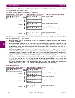
If no trigger is assigned in the
DEMAND TRIGGER
setting and the
CRNT DEMAND METHOD
is "Block Interval", use cal-
culating method #2. If a trigger is assigned, the maximum allowed time between 2 trigger signals is 60 minutes. If
no trigger signal appears within 60 minutes, demand calculations are performed and available and the algorithm
resets and starts the new cycle of calculations. The minimum required time for trigger contact closure is 20
μ
s.
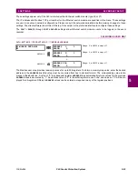
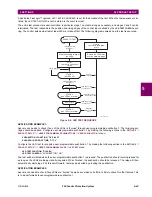
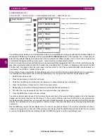
CALCULATION METHOD 3: ROLLING DEMAND
This method calculates a linear average of the quantity (RMS current, real power, reactive power, or apparent power) over
the programmed demand time interval, in the same way as Block Interval. The value is updated every minute and indicates
the demand over the time interval just preceding the time of update.
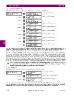
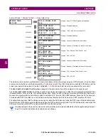
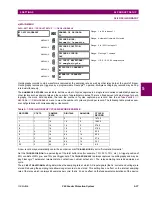
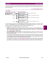
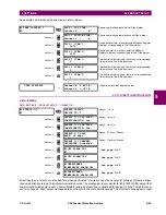
5.2.11 USER-PROGRAMMABLE LEDS
a) MAIN MENU
PATH: SETTINGS
Ö
PRODUCT SETUP
ÖØ
USER-PROGRAMMABLE LEDS
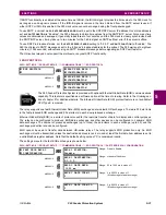
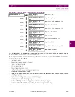
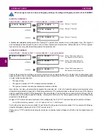
b) LED TEST
PATH: SETTINGS
Ö
PRODUCT SETUP
ÖØ
USER-PROGRAMMABLE LEDS
Ö
LED TEST
When enabled, the LED test can be initiated from any digital input or user-programmable condition such as user-program-
mable pushbutton. The control operand is configured under the
LED TEST CONTROL
setting. The test covers all LEDs,
including the LEDs of the optional user-programmable pushbuttons.
The test consists of three stages.
1.
All 62 LEDs on the relay are illuminated. This is a quick test to verify if any of the LEDs is “burned”. This stage lasts as
long as the control input is on, up to a maximum of 1 minute. After 1 minute, the test will end.
2.
All the LEDs are turned off, and then one LED at a time turns on for 1 second, then back off. The test routine starts at
the top left panel, moving from the top to bottom of each LED column. This test checks for hardware failures that lead
to more than one LED being turned on from a single logic point. This stage can be interrupted at any time.
3.
All the LEDs are turned on. One LED at a time turns off for 1 second, then back on. The test routine starts at the top left
panel moving from top to bottom of each column of the LEDs. This test checks for hardware failures that lead to more
than one LED being turned off from a single logic point. This stage can be interrupted at any time.
When testing is in progress, the LEDs are controlled by the test sequence, rather than the protection, control, and monitor-
ing features. However, the LED control mechanism accepts all the changes to LED states generated by the relay and
stores the actual LED states (on or off) in memory. When the test completes, the LEDs reflect the actual state resulting from
relay response during testing. The reset pushbutton will not clear any targets when the LED Test is in progress.
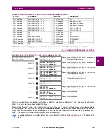
USER-PROGRAMMABLE
LEDS
LED TEST
See below
MESSAGE
TRIP & ALARM
LEDS
MESSAGE
USER-PROGRAMMABLE
LED1
MESSAGE
USER-PROGRAMMABLE
LED2
↓
MESSAGE
USER-PROGRAMMABLE
LED48
LED TEST
LED TEST FUNCTION:
Disabled
Range: Disabled, Enabled.
MESSAGE
LED TEST CONTROL:
Off
Range: FlexLogic™ operand
NOTE
Summary of Contents for F60 UR Series
Page 2: ......
Page 4: ......
Page 30: ...1 20 F60 Feeder Protection System GE Multilin 1 5 USING THE RELAY 1 GETTING STARTED 1 ...
Page 48: ...2 18 F60 Feeder Protection System GE Multilin 2 2 SPECIFICATIONS 2 PRODUCT DESCRIPTION 2 ...
Page 126: ...4 30 F60 Feeder Protection System GE Multilin 4 2 FACEPLATE INTERFACE 4 HUMAN INTERFACES 4 ...
Page 354: ...5 228 F60 Feeder Protection System GE Multilin 5 9 TESTING 5 SETTINGS 5 ...
Page 382: ...6 28 F60 Feeder Protection System GE Multilin 6 5 PRODUCT INFORMATION 6 ACTUAL VALUES 6 ...
Page 398: ...8 8 F60 Feeder Protection System GE Multilin 8 2 FAULT LOCATOR 8 THEORY OF OPERATION 8 ...
Page 414: ...A 14 F60 Feeder Protection System GE Multilin A 1 PARAMETER LIST APPENDIXA A ...
Page 492: ...B 78 F60 Feeder Protection System GE Multilin B 4 MEMORY MAPPING APPENDIXB B ...
Page 530: ...D 10 F60 Feeder Protection System GE Multilin D 1 IEC 60870 5 104 APPENDIXD D ...
Page 542: ...E 12 F60 Feeder Protection System GE Multilin E 2 DNP POINT LISTS APPENDIXE E ...
Page 558: ...x F60 Feeder Protection System GE Multilin INDEX ...


