284
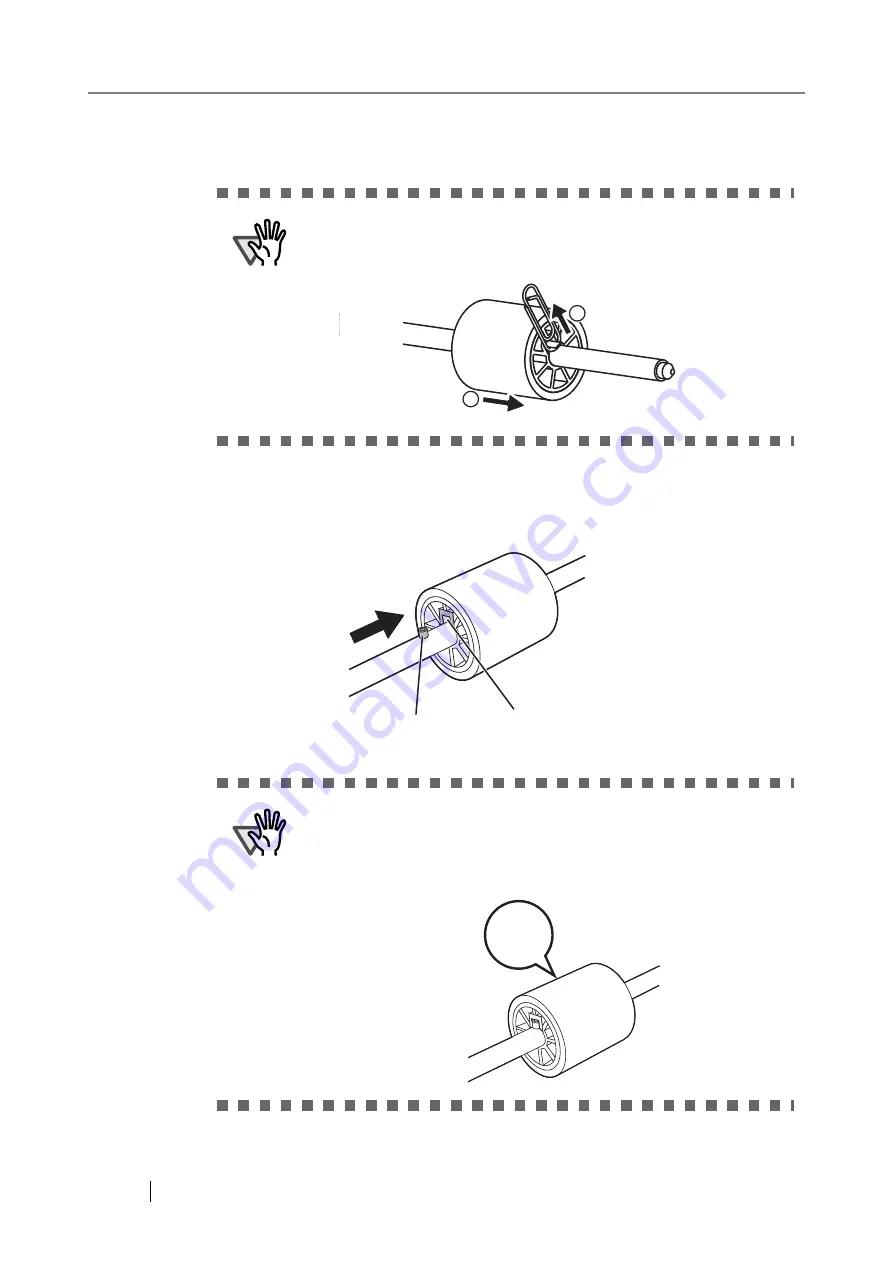
5. Remove the pick roller from the shaft.
Lift up the lock tab and slide the pick roller off the shaft.
6. Attach the new pick roller.
Insert the shaft into the new pick roller, aligning the protruding pin on the shaft with the
matching notch in the pick roller.
ATTENTION
Take care if lifting the pick roller lock tab with your fingernail as it
may get chipped or broken. If worried, try lifting the tab using a
paper clip as shown in the following diagram.
ATTENTION
Make sure that the pick roller shaft is fully inserted. If it is not cor-
rectly attached, document jams and other feeding errors may occur.
You should hear a "click" when the pick roller shaft is inserted cor-
rectly. Make sure you hear this noise when inserting the shaft into
the pick roller.
1
2
Pin on shaft
Pick roller notch
"Click"
Summary of Contents for FI-6000NS
Page 1: ...P3PC 1852 06ENZ0 ...
Page 2: ......
Page 10: ...x ...
Page 28: ...xxviii ...
Page 70: ...42 3 Press the Connect button The Login screen appears ...
Page 78: ...50 5 Press the Now button The system is restarted ...
Page 122: ...94 4 Press the Add button The screen for adding a network printer is displayed ...
Page 202: ...174 ...
Page 296: ...268 ...
Page 316: ...288 6 Press the OK button The Maintenance screen is shown again ...
Page 348: ...320 ...
Page 358: ...330 ...
Page 362: ...334 ...
Page 426: ...398 ...
Page 427: ...Network Scanner fi 6000NS Operator s Guide 399 D Appendix D Glossary ...
Page 432: ...404 ...


