


20
1.3 Printing Specifications
DX100 Service Manual
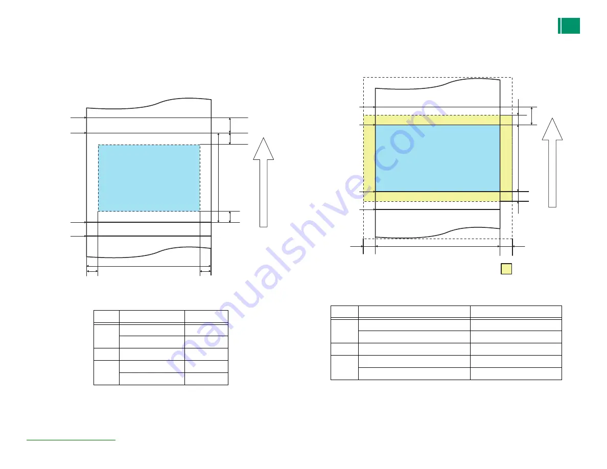
1.3.4 Printable Area
Bordered Printing Mode
Figure 1-1. Bordered Printing Mode
Note : Margins can be set to 0 mm but some amount of margin may still be present.
Borderless Printing Mode
Figure 1-2. Borderless Printing Mode
Ver.1
Symbol
Item
Value
a
Print Top
0 mm
Print Bottom
0 mm
b
Cut Off Amount
5 mm
c
Side (Home)
0 mm
Side (Full)
0 mm
Printing Area
Preceding Page
Subsequent Page
b
a
a
c
c
Auto Cut
position
Print Le
ngth
Paper Width
Auto Cut
position
Auto Cut
position
Auto Cut
position
Paper
Feed
Symbol
Item
Value
a
Print Top Wasted Amount
1.7 mm
Print Bottom Wasted Amount
1.7 mm
b
Print Top Cut Off Amount
5 mm
c
Side Wasted Amount (Home)
1.7 mm
Side Wasted Amount (Full)
1.7 mm
Printing Area
Preceding Page
Subsequent Page
b
a
a
c
c
Auto Cut
position
Print Length
Paper Width
Auto Cut
position
Auto Cut
position
Auto Cut
position
Wasted Area
Pa
pe
r F
eed
Summary of Contents for Frontier-S DX100
Page 13: ...13 DX100 Service Manual 7 3 Board Layout Diagram 299 7 4 Board Voltage List 303...
Page 14: ...C H A P T E R 1 PRODUCTDESCRIPTION...
Page 29: ...C H A P T E R 2 OPERATINGPRINCIPLES...
Page 46: ...C H A P T E R 3 TROUBLESHOOTING...
Page 76: ...C H A P T E R 4 DISASSEMBLY ASSEMBLY...
Page 208: ...C H A P T E R 5 ADJUSTMENT...
Page 279: ...C H A P T E R 6 MAINTENANCE...
Page 296: ...C H A P T E R 7 APPENDIX...
Page 298: ...298 7 2Connector Summary DX100 Service Manual 7 2 Connector Summary PW sensor...
Page 302: ...302 7 3Board Layout Diagram DX100 Service Manual Power Supply Board...


