CPX230NWB ALARM CONTROL PANEL – INSTALLER MANUAL
20 / 144
EN
Not lit: partition not armed in night mode.
3.
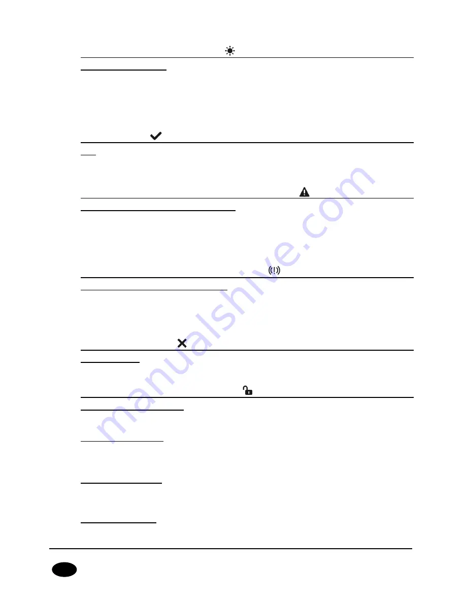
STAY Day mode arming symbol
– indicated with diodes C (partition P1)
and 3 (partition P2)
Blinks slowly: exit time countdown,
Blinks quickly: entry time countdown,
Lit continuously: partition armed in day mode,
Not lit: partition not armed in day mode.
4.
READY symbol
– indicated with diodes D (partition P1) and 4 (partition
P2)
Lit when all zones (without the “ignore when arming” option selected) are in nominal
condition (not triggered).
5.
Partition input or output sabotage/failure symbol
– indicated with diodes
E (partition P1) and 5 (partition P2)
Blinks quickly: no longer present, but there were failures/sabotage of inputs or outputs
assigned to the partition,
Lit continuously: there are failures/sabotage of inputs or outputs assigned to the
partition.
6.
Partition alarm/alarm memory symbol
– indicated with diodes F
(partition P1) and 6 (partition P2)
Blinks quickly: no longer present, but there were alerts from zones assigned to the
partition,
Lit continuously: there is an alarm from a zone assigned to the partition.
7.
Line bypass symbol
– indicated with diodes G (partition P1) and 7
(partition P2)
Lit when at least one zone belonging to the partition is locked out (bypassed).
8.
DISARM Partition disarming symbol
– indicated with diodes H (partition
P1) and 8 (partition P2)
Lit when the given partition is disarmed, e.g. in DISARM mode.
9.
Diodes A-H (white)
A row of diodes used to indicate the status of partition P1 (example: when lit, “B” diode
means partition P1 is armed in SLEEP night mode).
10.
Diodes 1-8 (white)
A row of diodes used to indicate the status of partition P2 (example: when lit, “3” diode
means partition P2 is armed in STAY day mode).
11.
Partition 1 (“P1”)
The P1 symbol means partition 1, to which diodes from A to H are assigned.


