79
POWER INSTRUMENTS
no output. The CT primary value of I1 is 200A. The primary voltage of U1 is
10000V, PT2 is 100V. Then let’s look how all the related registers are set.
The first record:
According to the table, the serial number of I1 is 9 ((14d8H)= 9); Conditions
in equation 1 determine the high limit. So “comparison mode” (14d9H) = 1(>).
CT1 is 200A, according to the relationship between the communication value
and numerical value. I=Rx X(CT1/5)/1000, so I1 is 180A. Then the limit is (14daH)
= 4500; Delay 5s, as the unit of Limit_t register is 10ms, so the delay time is
(14dbH) = 500; Alarming but no waveform triggering, “waveform capture” (14dcH)
= 0.
The second record:
According to the table, the serial number of U1 is 1 ((14ddH) = 1);
Conditions in equation 1 determine the low limit. So “comparison mode” (14d9H)
= 3(<); PT1 is 10000V, according to the relationship between the communication
value and numerical value, U=Rx X (PT1 / PT2) /10, so the register value should
be 998; Delay 10s, as the unit of Limit_t register is 10ms, so the delay time is
(14e0H) = 1000; Alarming but no waveform triggering, so “waveform capture”
(14e1H) = 0.
Settings between the two records:
“Alarming output” of the 1st, 2nd(101fH) = 0x0003; No hardware output,
(1020H)=0; (1021H)=0;(1022H)=0; (1023H)=0; logical and(1024H)=0x0001; At
last, the” alarming enable”, (101dH) =1.
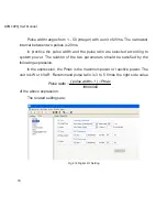
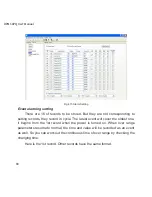
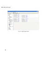
Here is a figture showing the alarming settings:
Summary of Contents for XPQ
Page 1: ...POWER INSTRUMENTS DPMS XPQ Multi Function Power Meter User Manual 1087 332...
Page 2: ......
Page 7: ...Chapter 1 Introduction Purpose Application Area Functions DPMS XPQ Series 5...
Page 13: ...Chapter 2 Installation Appearance and Dimensions Installation Method Wiring 11...
Page 30: ...28 DPMS XPQ User Manual 6 2LL 2CT Fig 2 23 2LL 2CT 7 2LL 1CT Fig 2 24 2LL 1CT...
Page 59: ...Chapter 4 Function and Software Functionality and Utility Software 57...
Page 68: ...66 DPMS XPQ User Manual Here is an example Fig 4 7 Demand Here is to set demand...
Page 90: ...88 DPMS XPQ User Manual Fig 4 20 Voltage Eligibility Ratio...
Page 126: ...124 DPMS XPQ User Manual...
Page 127: ...125 Appendix Appendix A Technical Data and Specifications Appendix B Ordering Information...
Page 133: ......

