

84
DPMS XPQ User Manual
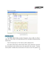
Waveform record
The DPMS XPQ can record 5 cycles of waveforms both before and after
the trigger point of the entire 6 input channels (U1, U2, U3, I1, I2 and I3). There
are 16 points for each cycle and a maximum of 5 waveform records.
There are three reasons for waveform triggering: DI changes, alarming and
manual triggering. Please refer to related chapters for more details.
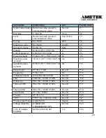
Format: w1~w7 recording time (w1:yyyy; w2:mm; w3:dd; w4:hh; w5:mm;
w6:ss; w7:ms).
w8-w10 indicates the trigger: (w8: DI triggering, Bit1,bit0 indicates DI1;
Bit3,bit2 indicates DI2; Bit5,bit4 indicates DI3 and Bit7,bit6 indicates DI4. “00”
indicates not trigger by DI, “01” indicates trigger by DI from off to on, “10”
indicates trigger by DI from on to off and “11” indicates a trigger by DI for any
changes. w9: alarming trigger, bit0~bit15 are corresponding to the 1st - 16th of
the 16 alarming groups. 1: alarming trigger capture; 0: alarming does not trigger
capture. w10: manual triggering.1:yes; 0:no.)
Then there are 10 cycle waveform of UA, 10 cycle waveform of IA, 10 cycle
waveform of UB, 10 cycle waveform of IB, 10 cycle waveform of UC, 10 cycle
waveform of IC. Please refer to the address table for more details.
The waveform record will set bit1 of “system status” to 1. At the same time,
corresponding flags will be set to 1 to indicate new data. The meter sets the
flag of the waveform record but does not clear it. It should be cleared after the
controller has read the data, then bit0 of system parameters will be set to 0.
Update rule: It checks out empty records from the first one, if there is no
blank record, it won’t take a new record. All records won’t be lost during power
off.
Summary of Contents for XPQ
Page 1: ...POWER INSTRUMENTS DPMS XPQ Multi Function Power Meter User Manual 1087 332...
Page 2: ......
Page 7: ...Chapter 1 Introduction Purpose Application Area Functions DPMS XPQ Series 5...
Page 13: ...Chapter 2 Installation Appearance and Dimensions Installation Method Wiring 11...
Page 30: ...28 DPMS XPQ User Manual 6 2LL 2CT Fig 2 23 2LL 2CT 7 2LL 1CT Fig 2 24 2LL 1CT...
Page 59: ...Chapter 4 Function and Software Functionality and Utility Software 57...
Page 68: ...66 DPMS XPQ User Manual Here is an example Fig 4 7 Demand Here is to set demand...
Page 90: ...88 DPMS XPQ User Manual Fig 4 20 Voltage Eligibility Ratio...
Page 126: ...124 DPMS XPQ User Manual...
Page 127: ...125 Appendix Appendix A Technical Data and Specifications Appendix B Ordering Information...
Page 133: ......