


93
POWER INSTRUMENTS
the CRC. Start and stop bits, and the parity bit, do not apply to the CRC. During
generation of the CRC, each 8-bit character is exclusive ORed with the register
contents. Then the result is shifted in the direction of the least significant bit
(LSB), with a zero filled into the most significant bit (MSB) position. The LSB is
extracted and examined. If the LSB was a 1, the register is then exclusive ORed
with a preset, fixed value. If the LSB was a 0, no exclusive OR takes place. This
process is repeated until eight shifts have been performed. After the last (eighth)
shift, the next 8-bit byte is exclusive ORed with the register current value, and
the process repeats for eight more shifts as described above. The final contents
of the register, after all the bytes of the message have been applied, is the
CRC value. When the CRC is appended to the message, the low-order byte is
appended first, followed by the high-order byte.
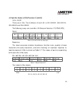
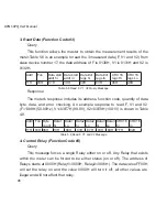
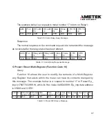
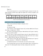
Format of communication
Explanation of frame
Addr Fun Data start
reg hi
Data start
reg lo
Data #of
regs hi
Data #of
regs lo
CRC 16
Hi
CRC 16
Lo
06H 03H 00H
00H
00H
21H
84H
65H
Table 5.3 Explanation of frame
In table 5.3, the meaning of each abbreviated word is,
Addr: address of slave device
Fun: function code
Data start reg hi: start register address high byte
Data start reg lo: start register address low byte
Data #of reg hi: number of register high byte
Data #of reg lo: number of register low byte
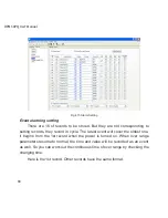
Summary of Contents for XPQ
Page 1: ...POWER INSTRUMENTS DPMS XPQ Multi Function Power Meter User Manual 1087 332...
Page 2: ......
Page 7: ...Chapter 1 Introduction Purpose Application Area Functions DPMS XPQ Series 5...
Page 13: ...Chapter 2 Installation Appearance and Dimensions Installation Method Wiring 11...
Page 30: ...28 DPMS XPQ User Manual 6 2LL 2CT Fig 2 23 2LL 2CT 7 2LL 1CT Fig 2 24 2LL 1CT...
Page 59: ...Chapter 4 Function and Software Functionality and Utility Software 57...
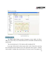
Page 68: ...66 DPMS XPQ User Manual Here is an example Fig 4 7 Demand Here is to set demand...
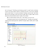
Page 90: ...88 DPMS XPQ User Manual Fig 4 20 Voltage Eligibility Ratio...
Page 126: ...124 DPMS XPQ User Manual...
Page 127: ...125 Appendix Appendix A Technical Data and Specifications Appendix B Ordering Information...
Page 133: ......