


24
DPMS XPQ User Manual
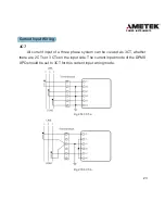
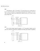
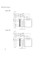
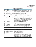
2CT
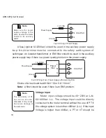
The difference in fig. 2.16 and fig. 2.15 is that there is not current input in
the I21 and I22 terminals. The I2 value is calculated from formula i1+i2+i3=0.
The current input mode of the DPMS XPQ should be set to 2CT for this current
input wiring mode.
Fig 2.16 2CT
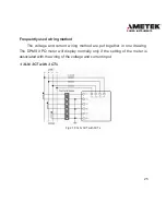
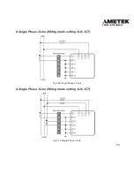
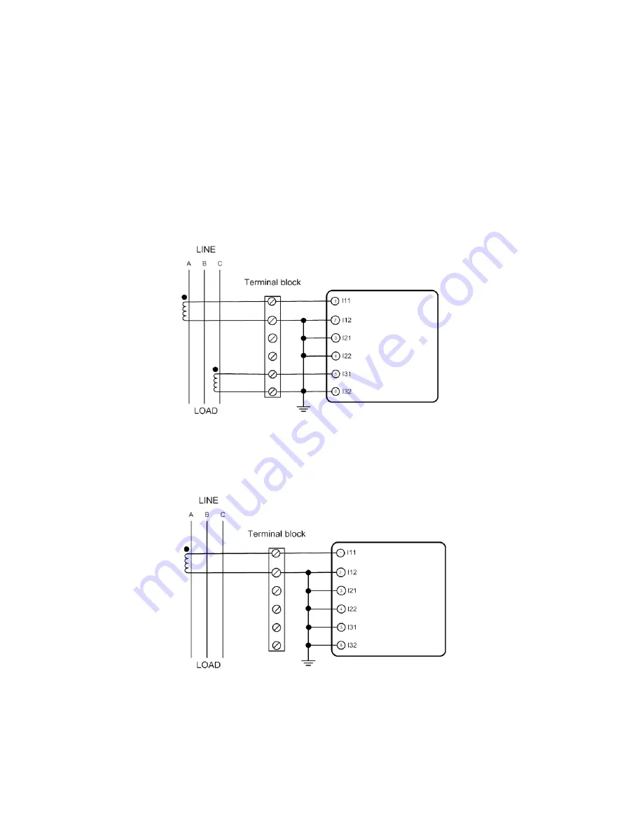
1CT
If it is a three phase balanced system, a 1 CT connection method can be
used. The other two currents are calculated according to the balance supposing.
Fig 2.17 1CT
Summary of Contents for XPQ
Page 1: ...POWER INSTRUMENTS DPMS XPQ Multi Function Power Meter User Manual 1087 332...
Page 2: ......
Page 7: ...Chapter 1 Introduction Purpose Application Area Functions DPMS XPQ Series 5...
Page 13: ...Chapter 2 Installation Appearance and Dimensions Installation Method Wiring 11...
Page 30: ...28 DPMS XPQ User Manual 6 2LL 2CT Fig 2 23 2LL 2CT 7 2LL 1CT Fig 2 24 2LL 1CT...
Page 59: ...Chapter 4 Function and Software Functionality and Utility Software 57...
Page 68: ...66 DPMS XPQ User Manual Here is an example Fig 4 7 Demand Here is to set demand...
Page 90: ...88 DPMS XPQ User Manual Fig 4 20 Voltage Eligibility Ratio...
Page 126: ...124 DPMS XPQ User Manual...
Page 127: ...125 Appendix Appendix A Technical Data and Specifications Appendix B Ordering Information...
Page 133: ......