33
POWER INSTRUMENTS
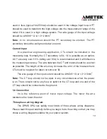
programmed as energy pulse output. For example, DO1 is used as energy
pulse output and DO2 is used as reactive energy pulse output. The pulse width
and pulse constant can be set.
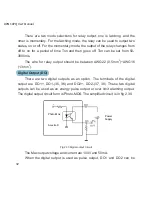
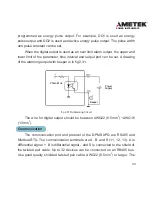
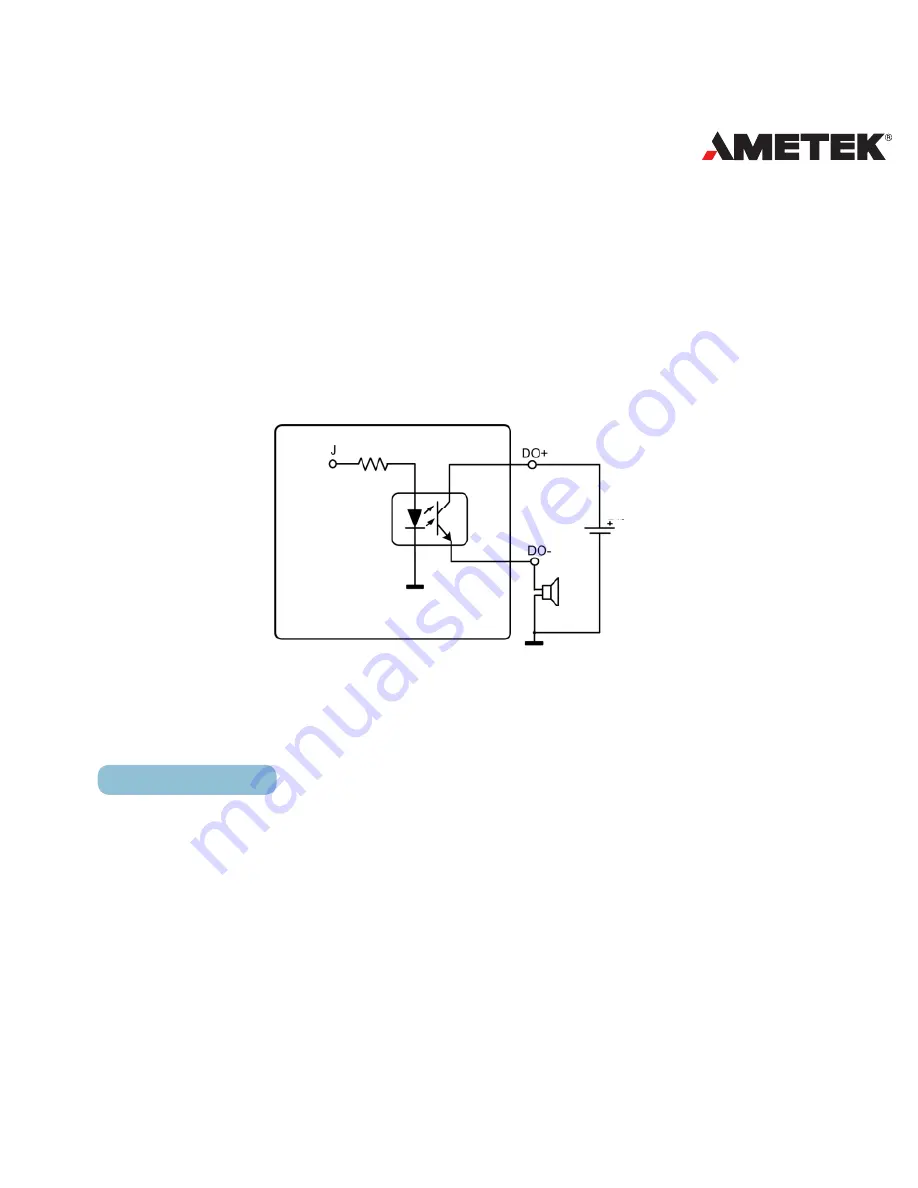
When the digital output is used as an over limit alarm output, the upper and
lower limit of the parameter, time interval and output port can be set. A drawing
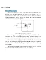
of the alarming output with beeper is in fig 2.31.
fig 2.31 Do Alarming Circult
The wire for digital output should be between AWG22 (0.5mm
2
) ~AWG16
(1.3mm
2
).
Communication
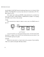
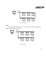
The communication port and protocol of the DPMS XPQ are RS485 and
Modbus-RTU. The communication terminals are A, B, and S (11, 12, 13). A is
differential , B is differential signal - and S is connected to the shield of
the twisted pair cable. Up to 32 devices can be connected on an RS485 bus.
Use good quality shielded twisted pair cable, AWG22 (0.5mm
2
) or larger. The
Fig 2.31 DO Alarming Circuit
Power
Supply
Photo -Mos
Acuvim -X
Beeper
Summary of Contents for XPQ
Page 1: ...POWER INSTRUMENTS DPMS XPQ Multi Function Power Meter User Manual 1087 332...
Page 2: ......
Page 7: ...Chapter 1 Introduction Purpose Application Area Functions DPMS XPQ Series 5...
Page 13: ...Chapter 2 Installation Appearance and Dimensions Installation Method Wiring 11...
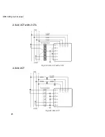
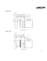
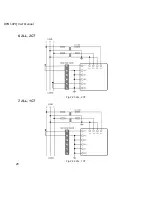
Page 30: ...28 DPMS XPQ User Manual 6 2LL 2CT Fig 2 23 2LL 2CT 7 2LL 1CT Fig 2 24 2LL 1CT...
Page 59: ...Chapter 4 Function and Software Functionality and Utility Software 57...
Page 68: ...66 DPMS XPQ User Manual Here is an example Fig 4 7 Demand Here is to set demand...
Page 90: ...88 DPMS XPQ User Manual Fig 4 20 Voltage Eligibility Ratio...
Page 126: ...124 DPMS XPQ User Manual...
Page 127: ...125 Appendix Appendix A Technical Data and Specifications Appendix B Ordering Information...
Page 133: ......

