


78
DPMS XPQ User Manual
“Alarming output to RO2” decides which alarm will be output to RO2. It is
set the same as RO1.
“Alarming output to DO1 setting”: When “Digital output mode” is set to “1”,
DO1 can be used as an alarming output. Which alarm will be output to RO2 is
set here. You need to do the same as what you do in setting RO1.
“Alarming output to DO2 setting”: The same as “Alarming output to DO1
setting”.
“Logical and between alarming setting”: The 16 alarming records are
divided into 8 groups. Each group has two records. The two alarms can be
logically “and” by controlling the logic switch. When two alarms are logically “and”,
the alarming works only when both are satisfied. If the switch is off, the two
alarms work independently.
The 8 groups are arranged as follows: according to their serial number, the
1st & 2nd make the 1st group as group A; the 3rd & 4th make the 2nd group as
group B; The 5th & 6th make the 3rd group as group C; 7th & 8th make the 4th
group as group D; 9rd &10th make the 5th group as group E; 11th & 12th make
the 6th group as group F; 13th & 14th make the 7th group as group G; 15th &
16th make the 8th group as group H.
This function is controlled by the low 8 bits of a 16 bits register, each bit
corresponds to a group. “1” means this function is turned on and “0” means off.
After finishing the previous settings, the alarming function is turned on.
We’ll show you an example of how to use the logical “and” in a group.
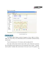
We set an event as follow: I1 greater than 180A, delay 5s for the 1st record;
U1 less than 9980V, delay 10s for the 2nd record. No waveform triggering,
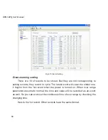
Summary of Contents for XPQ
Page 1: ...POWER INSTRUMENTS DPMS XPQ Multi Function Power Meter User Manual 1087 332...
Page 2: ......
Page 7: ...Chapter 1 Introduction Purpose Application Area Functions DPMS XPQ Series 5...
Page 13: ...Chapter 2 Installation Appearance and Dimensions Installation Method Wiring 11...
Page 30: ...28 DPMS XPQ User Manual 6 2LL 2CT Fig 2 23 2LL 2CT 7 2LL 1CT Fig 2 24 2LL 1CT...
Page 59: ...Chapter 4 Function and Software Functionality and Utility Software 57...
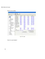
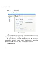
Page 68: ...66 DPMS XPQ User Manual Here is an example Fig 4 7 Demand Here is to set demand...
Page 90: ...88 DPMS XPQ User Manual Fig 4 20 Voltage Eligibility Ratio...
Page 126: ...124 DPMS XPQ User Manual...
Page 127: ...125 Appendix Appendix A Technical Data and Specifications Appendix B Ordering Information...
Page 133: ......