103
POWER INSTRUMENTS
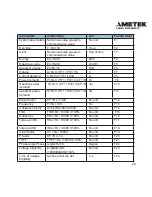
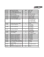
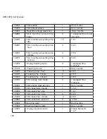
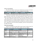
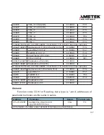
103FH
Apparent power measuring
mode
1
0,1
1040H
DI triggering demand
synchronization enable
0
0~4
1041H
DI triggering condition
1
1~3
To know more about these parameters, please refer to chapters 3 and 4.
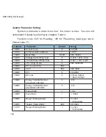
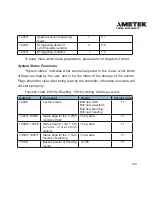
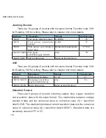
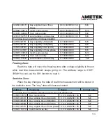
System Status Parameter
“System status” indicates what events happened in the meter, what kinds
of flags are read by the user and to be the index of the storage of the events.
Flags should be clear after being read by the controller, otherwise new data will
not store properly.
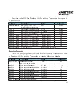
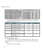
Function code: 03H for Reading, 10H for writing, data type: word.
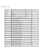
Address
Parameter
Range
Format code
1046H
system status
Bit0:new SOE
Bit1:new waveform
Bit2:new alarming
Bit3:new trending
F1
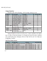
1047H~105AH
Status flags for the 1~20th
records of SOE
1:new data
F1
105BH~105FH
Status flags for the 1~5th
r e c o r d s o f w a v e f o r m
capture
1:new data
F1
1060H~106FH
Status flags for the 1~16th
records of alarming
1:new data
F1
1070H
Backup pointer of trending
record
0~355
F1
Summary of Contents for XPQ
Page 1: ...POWER INSTRUMENTS DPMS XPQ Multi Function Power Meter User Manual 1087 332...
Page 2: ......
Page 7: ...Chapter 1 Introduction Purpose Application Area Functions DPMS XPQ Series 5...
Page 13: ...Chapter 2 Installation Appearance and Dimensions Installation Method Wiring 11...
Page 30: ...28 DPMS XPQ User Manual 6 2LL 2CT Fig 2 23 2LL 2CT 7 2LL 1CT Fig 2 24 2LL 1CT...
Page 59: ...Chapter 4 Function and Software Functionality and Utility Software 57...
Page 68: ...66 DPMS XPQ User Manual Here is an example Fig 4 7 Demand Here is to set demand...
Page 90: ...88 DPMS XPQ User Manual Fig 4 20 Voltage Eligibility Ratio...
Page 126: ...124 DPMS XPQ User Manual...
Page 127: ...125 Appendix Appendix A Technical Data and Specifications Appendix B Ordering Information...
Page 133: ......

