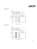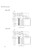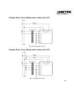
17
POWER INSTRUMENTS
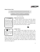
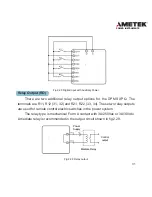
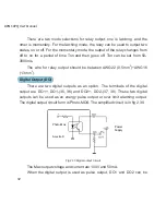
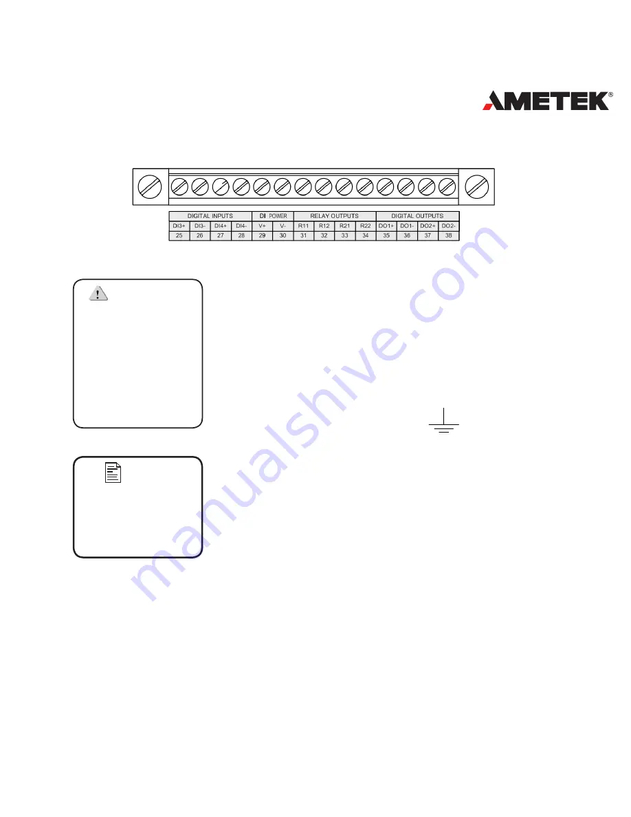
Extend Terminal Strip
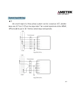
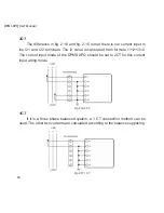
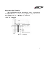
Fig 2.7 Terminal Strips
Safety Earth Connection
Before doing the meter wiring connection, please
make sure that the switch gear has a safety Earth
system. Connect the meter safety earth terminal to the
switch gear safety earth system. The following safety
earth symbol is used in this user’s manual.
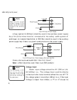
Auxiliary Power
The auxiliary power supply of the meter is 100-
240Vac (50/60Hz) or 100-300Vdc. The meter’s typical
power consumption is less than 2W. A regulator or a
UPS should be used when the power supply undulates
too much. The terminals for the auxiliary power supply
are 20, 22 and 24 (L, N, G). A switch or circuit-breaker should be included in the
building installation, and it should be in close proximity to the equipment and
within easy reach of the operator, and it should be marked as the disconnecting
device for the equipment.
DANEROUS
Only qualified personnel
s h o u l d d o t h e w i r e
connection work. Make
sure the power supply
is off and all the wires
are powerless. Failure to
observe this may result
in severe injury or death.
Note
Make sure the auxiliary
power terminal of the
meter, G, is connected
to the safety Earth of
switchgear.
Summary of Contents for XPQ
Page 1: ...POWER INSTRUMENTS DPMS XPQ Multi Function Power Meter User Manual 1087 332...
Page 2: ......
Page 7: ...Chapter 1 Introduction Purpose Application Area Functions DPMS XPQ Series 5...
Page 13: ...Chapter 2 Installation Appearance and Dimensions Installation Method Wiring 11...
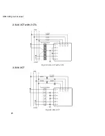
Page 30: ...28 DPMS XPQ User Manual 6 2LL 2CT Fig 2 23 2LL 2CT 7 2LL 1CT Fig 2 24 2LL 1CT...
Page 59: ...Chapter 4 Function and Software Functionality and Utility Software 57...
Page 68: ...66 DPMS XPQ User Manual Here is an example Fig 4 7 Demand Here is to set demand...
Page 90: ...88 DPMS XPQ User Manual Fig 4 20 Voltage Eligibility Ratio...
Page 126: ...124 DPMS XPQ User Manual...
Page 127: ...125 Appendix Appendix A Technical Data and Specifications Appendix B Ordering Information...
Page 133: ......

