12
DPMS XPQ User Manual
Note:
Before trying to operate the meter, note the functions according to its
pattern. The installation method is introduced in this chapter. Please read this
chapter carefully before beginning installation work.
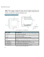
Appearance and Dimensions
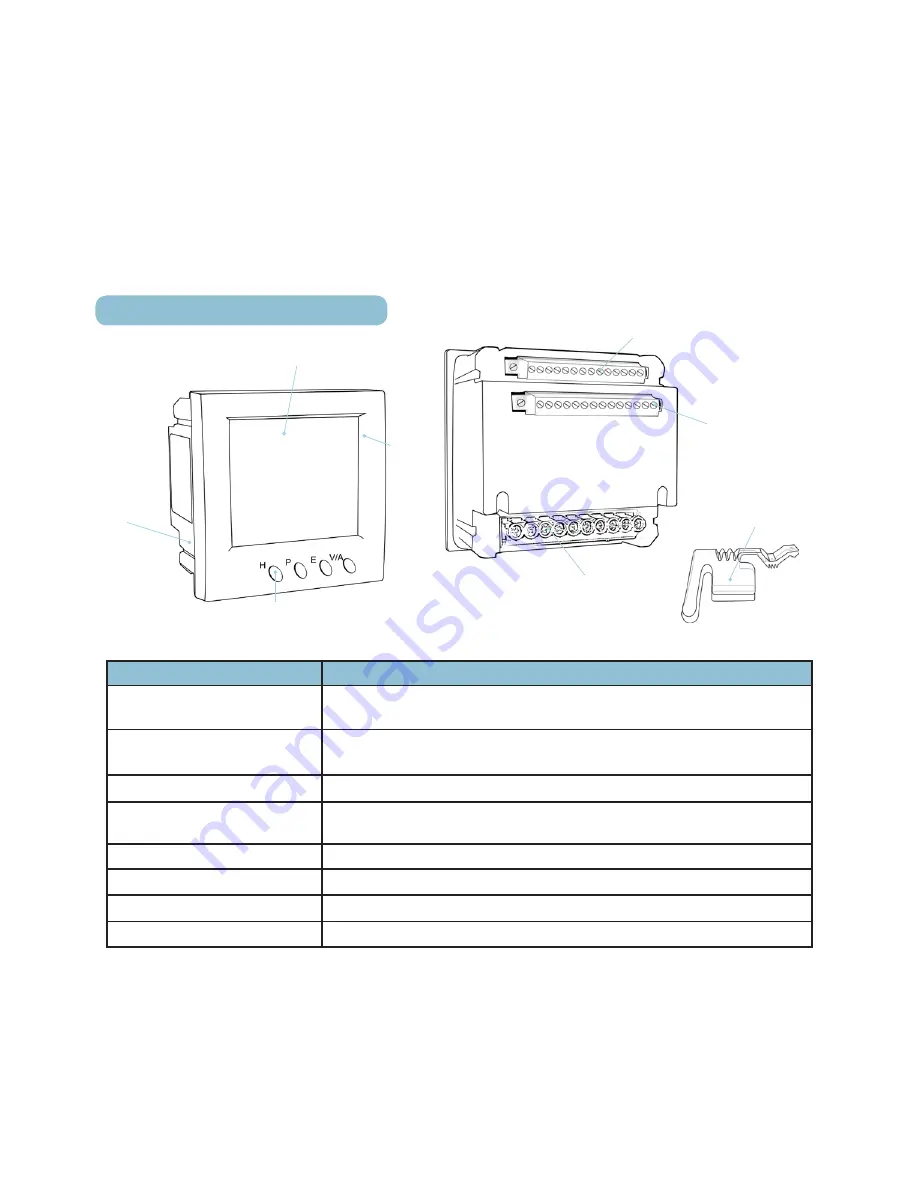
Fig 2.1 Appearance of the DPMS XPQ
PART NAME
DESCRIPTION
1. Enclosure
The DPMS XPQ enclosures are made of high strength anti-
combustible engineered plastic
2. Front
Casing After the installation, this part is before the panel. The color of
the front casing is optional
3. LCD
Display Large bright blue backlight LCD Display
4. Key
Four keys are used to select display and to set parameters of the
meter
5. Input Wiring
Terminals Used for Voltage and Current input
6. Auxiliary Wiring
Terminals Used for auxiliary power, communication and DI
7. Extend Wiring
Terminals Auxiliary I/O wiring terminals
8. Installation Clip
The clips are used for fixing the meter to the panel
Table2.1 Part Names of the DPMS XPQ
3
1
2
4
8
5
7
6
Summary of Contents for XPQ
Page 1: ...POWER INSTRUMENTS DPMS XPQ Multi Function Power Meter User Manual 1087 332...
Page 2: ......
Page 7: ...Chapter 1 Introduction Purpose Application Area Functions DPMS XPQ Series 5...
Page 13: ...Chapter 2 Installation Appearance and Dimensions Installation Method Wiring 11...
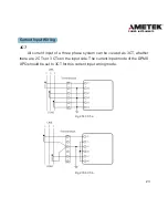
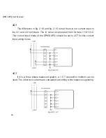
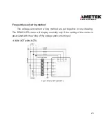
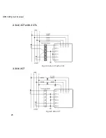
Page 30: ...28 DPMS XPQ User Manual 6 2LL 2CT Fig 2 23 2LL 2CT 7 2LL 1CT Fig 2 24 2LL 1CT...
Page 59: ...Chapter 4 Function and Software Functionality and Utility Software 57...
Page 68: ...66 DPMS XPQ User Manual Here is an example Fig 4 7 Demand Here is to set demand...
Page 90: ...88 DPMS XPQ User Manual Fig 4 20 Voltage Eligibility Ratio...
Page 126: ...124 DPMS XPQ User Manual...
Page 127: ...125 Appendix Appendix A Technical Data and Specifications Appendix B Ordering Information...
Page 133: ......


