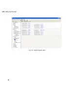

82
DPMS XPQ User Manual
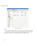
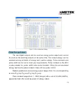
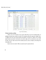
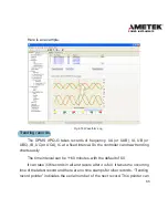
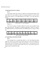
Fig 4.16 Alarm Log
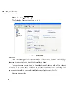
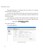
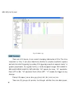
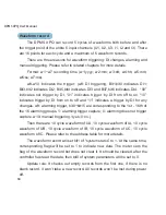
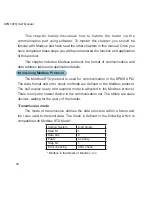
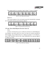
SOE Function
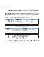
There are 4 DI inputs, it can record changing information of DIs. The time
resolution is 1ms. It can also determine whether to enable waveform capture
and which kind of triggering by setting “DI triggering waveform capture mode” in
system parameters. Its register forms a 16-bit unsigned integer. Bit1,bit0=DI1;
Bit3,bit2=DI2;Bit5,bit4=DI3; Bit7,bit6=DI4. “00” stands for none, “01” stands for
from OFF to ON, “10” stands for from ON to OFF ,“11” stands for trigger at any
change.
Format: DI status | occur time yyyy |mm | dd | hh | mm | ss | ms
There are 20 groups of records, it will begin with the first one after power
Summary of Contents for XPQ
Page 1: ...POWER INSTRUMENTS DPMS XPQ Multi Function Power Meter User Manual 1087 332...
Page 2: ......
Page 7: ...Chapter 1 Introduction Purpose Application Area Functions DPMS XPQ Series 5...
Page 13: ...Chapter 2 Installation Appearance and Dimensions Installation Method Wiring 11...
Page 30: ...28 DPMS XPQ User Manual 6 2LL 2CT Fig 2 23 2LL 2CT 7 2LL 1CT Fig 2 24 2LL 1CT...
Page 59: ...Chapter 4 Function and Software Functionality and Utility Software 57...
Page 68: ...66 DPMS XPQ User Manual Here is an example Fig 4 7 Demand Here is to set demand...
Page 90: ...88 DPMS XPQ User Manual Fig 4 20 Voltage Eligibility Ratio...
Page 126: ...124 DPMS XPQ User Manual...
Page 127: ...125 Appendix Appendix A Technical Data and Specifications Appendix B Ordering Information...
Page 133: ......