

81
POWER INSTRUMENTS
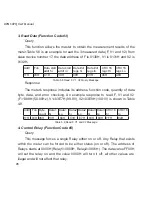
address
parameter
range
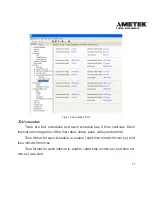
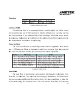
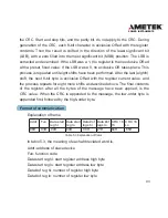
1540H
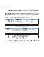
First group: alarming status
0~65536
1541H
First group: parameter number
0~246
1542H
First group: over range or reset value
Related with parameters
1543H~1549H First group: occur time: yyyy mm:dd:hh:
mm:ss:ms
time
Table 4-3 alarming status of the 1st record
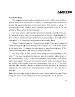
“alarming status” indicates information of the current status. It is a 16-bit
unsigned integer. Serial number is stored in the high 8 bits. Bit1 indicates logical
and.
Bit1=1,yes; Bit1=0,no. Bit0 indicates alarming is to setup or to recover.
Bit0=1, setup; Bit0=0, recover. Undefined bits are 0.
“Serial number” indicates which parameter is recorded.
“Value” indicates alarming limit value.
“Time” indicates the time with accuracy of ms.
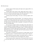
Alarming event will set bit2 of “system status” to 1. At the same time,
corresponding flags will be set to 1 to indicate new data. It should be cleared
after the controller has read the data, then bit2 of the system parameter will be
set to 0.
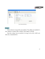
Note:
alarming records will not be lost during power off. The pointer will
point to the 1st record after it is powered on again.
Here is an example:
Summary of Contents for XPQ
Page 1: ...POWER INSTRUMENTS DPMS XPQ Multi Function Power Meter User Manual 1087 332...
Page 2: ......
Page 7: ...Chapter 1 Introduction Purpose Application Area Functions DPMS XPQ Series 5...
Page 13: ...Chapter 2 Installation Appearance and Dimensions Installation Method Wiring 11...
Page 30: ...28 DPMS XPQ User Manual 6 2LL 2CT Fig 2 23 2LL 2CT 7 2LL 1CT Fig 2 24 2LL 1CT...
Page 59: ...Chapter 4 Function and Software Functionality and Utility Software 57...
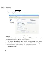
Page 68: ...66 DPMS XPQ User Manual Here is an example Fig 4 7 Demand Here is to set demand...
Page 90: ...88 DPMS XPQ User Manual Fig 4 20 Voltage Eligibility Ratio...
Page 126: ...124 DPMS XPQ User Manual...
Page 127: ...125 Appendix Appendix A Technical Data and Specifications Appendix B Ordering Information...
Page 133: ......