2-1
DX380LC-7
2
Operating Controls
The "Operating Controls" section consists of the following
groups:
1.
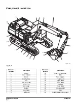
"Component Locations" on page 2-2
2.
3.
"Operational Controls and Panels" on page 2-7
4.
"Display Monitor" on page 2-26
5.
6.
"Around View Monitoring (AVM) System" on page 2-66
7.
"Proximity Alarm System" on page 2-69
8.
"Heater and Air Conditioner Control Panel" on page 2-72
9.
10. "Miscellaneous Electrical Devices" on page 2-79
11. "Seat Adjustment" on page 2-81
12. "Seat Belt" on page 2-85
13. "Engine Emergency Stop Switch" on page 2-86
14. "Emergency Exit Glass Breaking Tool" on page 2-86
15. "Miscellaneous Convenience Devices" on page 2-87
16. "Miscellaneous Access Covers and Doors" on page 2-93
17. "Air Gun and Compressor (If Equipped)" on page 2-95
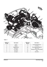
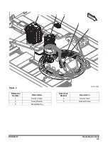
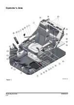
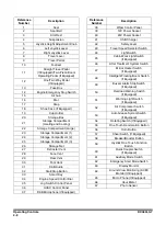
Each group is explained with a point location drawing or photo
and a brief description of each control, switch, gauge or valve.
Warning symbols will appear above the gauges on the display
monitor when a problem with the machine is detected.
The operator should monitor machine functions on the display
monitor to ensure the machine is operating properly.
NOTE:
The Illustrations in this manual showing details or
attachments that may look different from your
machine. The function is not changed depending on
the position of the switch or menu.
NOTICE
When any one or more of the warning symbols on the
control console comes "ON", immediately stop operation.
Investigate and correct the problem before proceeding with
operation.

