DX380LC-7
Operation
3-28
Work Levers (Joysticks) (ISO Pattern)
NOTE:
When starting work, move work levers (joysticks)
slowly and check movement of swing and front
attachment.
This equipment is manufactured using the lever control pattern
described in ISO standards. Do not change valving, hoses, etc.,
that would change this control pattern. The boom, arm and
bucket movements and swing direction of work levers
(joysticks)
are as follows:
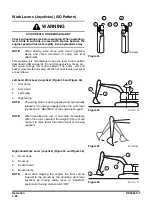
Left-hand Work Lever (Joystick) (Figure 33 and Figure 34)
1.
Arm dump
2.
Arm crowd
3.
Left swing
4.
Right swing
NOTE:
The swing brake is spring applied and hydraulically
released. It is always engaged when the work lever
(joystick) is in "NEUTRAL" or the engine is stopped.
NOTE:
When operating the arm, it may stop momentarily.
When the arm is operated, the weight of the arm can
cause it to move faster than the amount of oil being
supplied.
Right-hand Work Lever (Joystick) (Figure 33 and Figure 36)
5.
Boom down
6.
Boom up
7.
Bucket crowd
8.
Bucket dump
NOTE:
Even after stopping the engine, the front can be
lowered to the ground by the operating work lever
(joystick) by moving safety lever to "UNLOCK"
position and turning starter switch "ON".
FG018404
1
2
4
3
5
6
8
7
Figure 33
WARNING
AVOID DEATH OR SERIOUS INJURY
Check surrounding area before swinging. When operating a
lever while in auto idle, proceed with caution because the
engine speed will increase rapidly. Keep bystanders away.
1
2
4
3
DS1701176
Figure 34
EX1300702
Figure 35
DS1701177
6
5
7
8
Figure 36

