background image

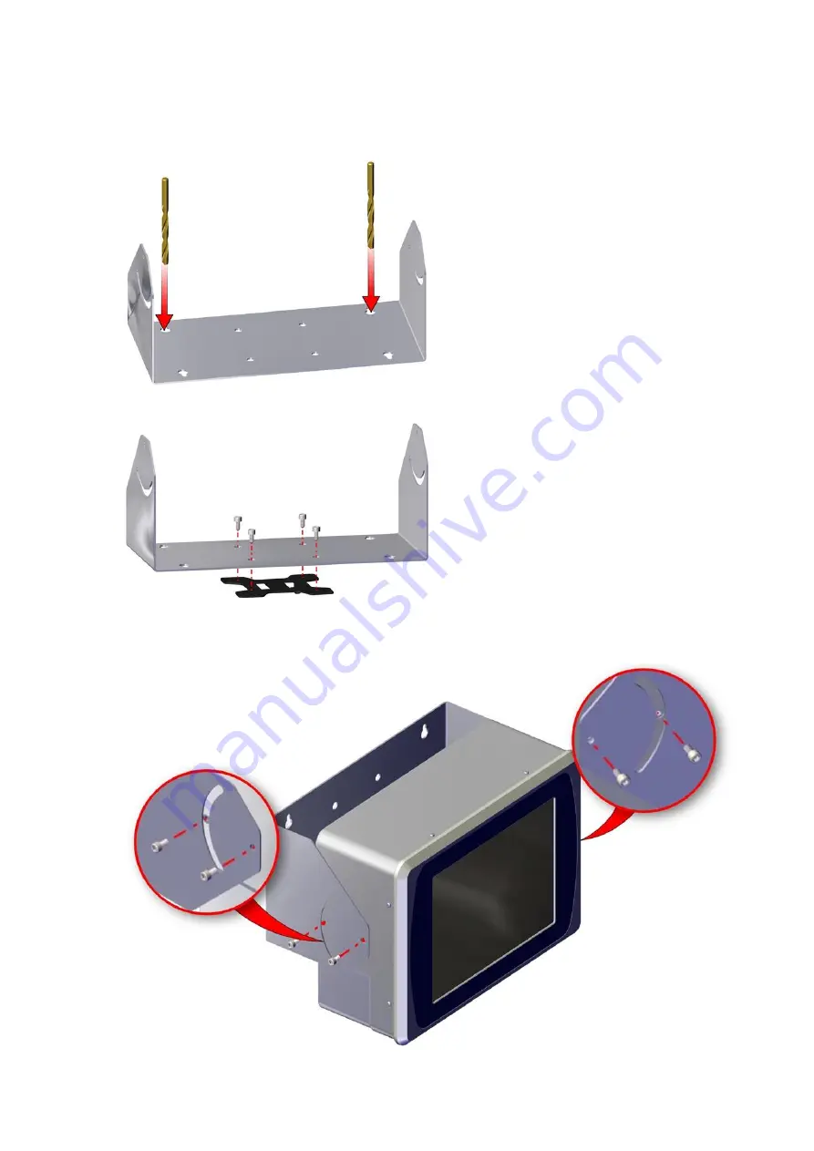
To mount the Gx-IC10 Controller:

1. Mount the bracket to a fixed vertical or horizontal surface. The bracket can be mounted

directly to a flat surface or installed on a VESA 75 mount.

Direct Installation

VESA 75 Installation

2. Mount the controller to the bracket.

INSTALLATION

27

EPT053091 - Issue 5 - 07 May 2021

Summary of Contents for Gx-OEM

Page 1: ...Gx Series Product Manual Gx150i Gx350i Gx OEM ...

Page 2: ...y the specification contained in this product manual without notice Domino Printing Sciences plc 2021 For sales service and inks please contact www buydomino com www domino printing com Domino UK Ltd Domino North America Bar Hill Cambridge CB23 8TU England Tel 01954 782551 Fax 01954 782874 1290 Lakeside Drive Gurnee IL 60031 U S A Tel 847 244 2501 Fax 847 244 1421 Amendment Record Amendment Date A...

Page 3: ...ments It is therefore essential that users are also familiar with these symbols and act accordingly It is important to Keep the manual during the lifetime of the equipment Pass the manual on to any subsequent holder or user of the equipment FCC NOTICE Note This equipment has been tested and found to comply with the limits for a Class A digital device pursuant to part 15 of the FCC Rules These limi...

Page 4: ...d ip open source licensing aspx SOFTWARE CREDITS Barcode Engine by TEC IT www tec it com Portions Copyright Morovia Corporation 2008 All Rights Reserved This product uses the following libraries The libraries and their use are covered by the GNU Lesser General Public License version 2 1 e2fsprogs 1 43 9 libext2fs lib e2p eudev 3 2 5 libraries kmod 24 utillinux 2 31 1 libblkid libfdisk libmount ico...

Page 5: ...Gx IC10 Controller 12 Gx OEM Controller 12 Print Heads 13 Standard Print Head 13 Multi Print Head 13 Print Head Configurations 14 Print Head Status Light 15 Specification 17 Controllers 17 Controller External Connections 18 Controller Electrical Supply 19 Environment 19 Pre installed Fonts 19 Print Heads 20 User Interface 21 PART 2 INSTALLATION 22 Unpacking 22 Controller and Print Head Location 22...

Page 6: ...yout Gx IC10 Gx OEM 46 I O Connection Examples Gx IC10 Gx OEM 47 Print Head Setup 53 Multi Print Head Socket Relocation 53 Combining Print Heads 57 Print Head Mounting 61 Print Head Orientation 62 Print Head Lever Kit Installation 63 Print Head Grounding 64 Print Head Group Assignment 64 Print Group Setup 65 Ink Type Restriction Setup 69 Ink Cartridge Installation 70 External Shaft Encoder Mode Se...

Page 7: ...90 SMB Server Message Block 91 Simple EDC 93 Promotional Coding 95 Language and Keyboard Setup 99 Date and Time 99 Manual Setup 100 NTP Setup 100 Label Editor Default Setup 101 Element Property Defaults 101 Content Property Defaults 101 Label Defaults 101 Alert Configuration 104 General Settings 105 Configuration Code Activation 105 Spares and Accessories 106 PART 3 OPERATION 107 Start Up 107 Assi...

Page 8: ...ecurity Mode 126 Log In 126 Log Out 127 Advanced Security 127 Enable Advanced Security Mode 127 Log In 127 Log Out 128 Enable Auto Log in 129 Disable Auto Log in 129 Change Current User Password 129 Reset Forgotten Password 129 Set Password Policy 130 Add New User 130 Change User Settings 131 Delete User 132 Add New User Group 132 Delete User Group 133 Change User Group Settings Access 133 Audit L...

Page 9: ...te Using Prompt at Print 167 Label Store and File Management 167 Select Existing Label 167 File Manager 168 Import Label 168 Export Label 169 Delete Label 170 Import Image 170 Import Font 171 Printer Diagnostics 172 Statistics 172 Statuses Alerts and Fault Finding 173 Statuses 173 Alerts 173 Print Quality Faults 185 PART 4 MAINTENANCE TROUBLESHOOTING 186 Ink Cartridge Replacement 186 Purge Blocked...

Page 10: ...Stop the print group before removing and or installing an ink cartridge Use only lint free wipes when cleaning the cartridge nozzles Clean cartridge nozzles according to the enclosed recommendations Protect the print heads from impact with proper adjustment and alignment of side rails and product guides Do not open any enclosed components of the controller or print heads They contain no user servi...

Page 11: ... is connected to ground Eye protection must be worn Protective clothing must be worn Use adequate protective gloves Consult the relevant Safety Data Sheet SDS Disconnect power before carrying out maintenance or repair Connect an earth terminal from the product to an appropriate ground source INKS AND FLUIDS INFORMATION Domino supplies Safety Data Sheets SDS giving specific safety information for e...

Page 12: ...d They must be collected for safe disposal after use After exposure to ink all possible traces must be washed off as soon as possible at the nearest washing facility Storage Printing inks must be stored in well ventilated buildings in areas set aside for the purpose and chosen for safety in case of fire All fluids must be stored in accordance with local regulations Fire Risk Observe all warnings g...

Page 13: ... distributor technician should ensure that the line the printer is installed on is appropriately grounded This means that all metallic items within 12 inches 300mm of the print head location must be securely grounded This should be checked with respect to the print head chassis ground using an Ohm Meter DVM or another suitable device It is essential that grounding is checked periodically and that ...

Page 14: ...cycling symbols It indicates that at the end of life the product battery you should dispose of it separately at an appropriate collection point and not place it in the normal domestic waste stream USA STATE OF CALIFORNIA BATTERY STATEMENT Perchlorate Material special handling may apply See www dtsc ca gov hazardouswaste perchlorate Contents 9 EPT053091 Issue 5 07 May 2021 ...

Page 15: ...on updating the software Description The Domino Gx Series is a range of thermal ink jet printers intended for printing fixed and variable data on products on manufacturing production lines For specific details contact your local support office Each Gx Series consists of 1 or more print heads with a cable connecting each print head to a controller A controller containing the electronic control syst...

Page 16: ...touch screen Setup configuration and label creation editing are done directly on the controller no external software required Note The Gx IC7 Controller configured with Gx150i software is a Gx150i Gx IC7 Controller SYSTEM DESCRIPTION 11 EPT053091 Issue 5 07 May 2021 ...

Page 17: ...configured with Gx350i software is a Gx350i Gx IC10 Controller Gx OEM Controller The Gx OEM Controller is designed to be integrated into machinery and fitted into control cabinets It is designed to be integrated with OEM production line systems The controller s settings and label creator editor are accessed using the web browser from any Ethernet connected PC Gx OEM Controller SYSTEM DESCRIPTION E...

Page 18: ...hen changing ink cartridges Note Consult Domino if stitch barcodes are required Standard Print Head The standard print head has a socket for connection to the controller at the top Standard Print Head Multi Print Head The multi print head has a socket connector that can be moved to the front or rear of the print head This allows the print head to be installed in areas with different space restrict...

Page 19: ...er 2 print groups 1 print head in each group or 1 print group of 2 print heads Gx350i Gx OEM Maximum of 4 print heads in the following different printing configurations Gx IC10 Gx OEM Controller 1 print group of 4 print heads or 2 print groups 2 print heads in each group or SYSTEM DESCRIPTION EPT053091 Issue 5 07 May 2021 14 ...

Page 20: ...he LED location is illustrated below Print Head Status LED Location The meaning of the LED colours and flashing pattern is described in the table below Light Pattern Idle Light Pattern Printing Description Off Off The print head has not yet booted up or the print head is not connected to the controller Blue Blinking Blue Blinking The print head is booting up or there is a connection fault SYSTEM D...

Page 21: ... Green Red Blinking No ink cartridge or the ink cartridge is empty Blue Green The print head is ready to print or is printing Blue Green Blinking The ink level is low or near empty Blue Red The ink cartridge is empty unable to continue printing SYSTEM DESCRIPTION EPT053091 Issue 5 07 May 2021 16 ...

Page 22: ...Print Heads Gx150i 2 Gx350i 4 Gx OEM 4 Maximum Number of Print Groups Gx150i 2 Gx350i 4 Gx OEM 4 Print Head Cable Length 3 6 12 or 25 metres Maximum Print Speed 300 m min at 60 DPI to 30 m min at 600 DPI horizontal resolution Maximum Print Height with stitch print heads Gx150i 1 x Print Head 12 7 mm 0 5 2 x Print Heads 25 18 mm 0 99 Gx350i 1 x Print Head 12 7 mm 0 5 2 x Print Heads 25 18 mm 0 99 3...

Page 23: ...00 mA Outputs 1 x Ground I O Terminal Block 1 Gx IC10 Gx OEM 1 x S2C 3 5mm 28 Way Terminal Block 4 x Product Detect Sensor Inputs 6 x General Purpose Inputs Max 24 V DC 1 A 8 x General Purpose Outputs Max 24 V DC 30 mA 2 x 24 V DC 300 mA Outputs 2 x Grounds I O Terminal Block 2 Gx IC10 Gx OEM 1 x S2C 3 5mm 18 Way Terminal Block 3 x Alarm Outputs Max 24 V DC 300 mA 4 x General Purpose Inputs Max 24...

Page 24: ...to 45 ºC 32 ºF to 113 ºF Operating Relative Humidity 20 80 RH Non Condensing 10 ºC Increase per hour IP Rating Gx IC7 N A Gx IC10 IP64 Gx OEM Controller N A Print Heads N A Pre installed Fonts Note To reduce the start up time it is recommended to remove unused fonts Pre installed fonts include Liberation Mono Regular Bold Italic Bold Italic Liberation Sans Regular Bold Italic Bold Italic Liberatio...

Page 25: ...h 50 9 mm 2 Weight 0 22 kg 0 48lbs Standard Print Head Dimensions Including Connector Ink Cartridge and Face Plate Height 165 mm 6 49 Width 54 mm 2 12 Depth 86 7 mm 3 41 Multi Print Head Dimensions Including Connector Height 152 mm 5 98 Width 28 5 mm 1 12 Depth 60 9 mm 2 39 Weight 0 22 kg 0 48lbs SYSTEM DESCRIPTION EPT053091 Issue 5 07 May 2021 20 ...

Page 26: ...idth 54 mm 2 12 Depth 91 6 mm 3 60 USER INTERFACE The QuickStep user interface is illustrated below QuickStep Interface Domino has developed QuickStep to be easy and intuitive to use Training times set up times and coding errors are all reduced with QuickStep SYSTEM DESCRIPTION 21 EPT053091 Issue 5 07 May 2021 ...

Page 27: ... any differences to Domino CONTROLLER AND PRINT HEAD LOCATION Position the controller and print heads Where they are electrically isolated from other equipment Where the temperature remains within the specified range see Environment on page 19 Where the relative humidity remains within the specified range see Environment on page 19 Close to an accessible power outlet to ensure power can be disconn...

Page 28: ...unt the bracket to a fixed vertical or horizontal surface The bracket can be mounted directly to a flat surface or installed on a VESA 75 mount Direct Installation VESA 75 Installation 2 Mount the controller to the bracket INSTALLATION 23 EPT053091 Issue 5 07 May 2021 ...

Page 29: ...3 If mounting to a vertical surface point the controller s electrical connectors and power switch downwards Incorrect Correct INSTALLATION EPT053091 Issue 5 07 May 2021 24 ...

Page 30: ...4 If mounting to a horizontal surface do not point the electrical connectors and power switch upwards beyond 0 Incorrect Correct End of procedure INSTALLATION 25 EPT053091 Issue 5 07 May 2021 ...

Page 31: ...nting bracket can be installed in orientation A or orientation B Orientation A may provide better access to the controller s electrical connectors when the controller is tilted Orientation A Orientation B INSTALLATION EPT053091 Issue 5 07 May 2021 26 ...

Page 32: ... to a fixed vertical or horizontal surface The bracket can be mounted directly to a flat surface or installed on a VESA 75 mount Direct Installation VESA 75 Installation 2 Mount the controller to the bracket INSTALLATION 27 EPT053091 Issue 5 07 May 2021 ...

Page 33: ...t the controller s electrical connectors and power switch downwards Incorrect Correct 4 If mounting to a horizontal surface do not point the electronic connectors and power switch upwards beyond 0 INSTALLATION EPT053091 Issue 5 07 May 2021 28 ...

Page 34: ... live electrical components Physical contact with live electrical components can result in an electric shock CAUTION Electricity Risk of damage to equipment Turn off the equipment and disconnect the power supply before disconnecting or making electrical connections When powered on the equipment contains live electrical components An incorrect electrical connection can damage the equipment INSTALLA...

Page 35: ...e devices to ensure trouble free operation CONTROLLER ELECTRICAL CONNECTIONS Gx IC7 WARNING Electricity Risk of injury Turn off the equipment and disconnect the power supply before disconnecting or making electrical connections When powered on the controller contains live electrical components Physical contact with live electrical components can result in an electric shock CAUTION Electricity Risk...

Page 36: ...live electrical components Physical contact with live electrical components can result in an electric shock CAUTION Electricity Risk of damage to equipment Turn off the equipment and disconnect the power supply before disconnecting or making electrical connections When powered on the equipment contains live electrical components An incorrect electrical connection can damage the equipment Gx IC10 C...

Page 37: ... controller s IP rating to be maintained To maintain the IP rating use the solid grommets to block holes in the seal that are not needed For easy access to the controller s USB sockets it is recommended to connect a USB extension cable to the controller through the protective cover and seal Required tools 2 5 mm and 4 mm hex keys To make electrical connections to the Gx IC10 Controller 1 Remove th...

Page 38: ... install the cover CAUTION Risk of equipment damage To ensure cables are not pulled out when the cover is removed check the cables have enough length between the internal seal and controller s electrical connectors If the cables are too short the cables and controller may be damaged by pulling when the cover is removed INSTALLATION 33 EPT053091 Issue 5 07 May 2021 ...

Page 39: ...al components Physical contact with live electrical components can result in an electric shock CAUTION Electricity Risk of damage to equipment Turn off the equipment and disconnect the power supply before disconnecting or making electrical connections When powered on the equipment contains live electrical components An incorrect electrical connection can damage the equipment INSTALLATION EPT053091...

Page 40: ...connecting or making electrical connections When powered on the controller contains live electrical components Physical contact with live electrical components can result in an electric shock CAUTION Electricity Risk of damage to equipment Turn off the equipment and disconnect the power supply before disconnecting or making electrical connections When powered on the equipment contains live electri...

Page 41: ...ption 1 Ground 3 24 V DC 4 A Input 2 Ground 4 24 V DC 4 A Input Encoder Connector Layout Gx IC7 controllers have 1 encoder connector Gx IC10 and Gx OEM controllers have 2 encoder connectors ENC1 and ENC2 RS422 standard The pin assignments are illustrated below D Sub Socket External View Pin Description Pin Description 1 24 V 6 Not Used 2 Ground 7 Not Used 3 Not Used 8 Encoder Channel B 4 Encoder C...

Page 42: ...able to connect print heads to the controller High Density D Sub Socket External View Pin Description Pin Description 1 Tx Transmit 9 Not Used 2 Ground 10 24 V 3 Tx Transmit 11 24 V 4 DET Detector 12 Ground 5 Ground 13 Ground 6 Rx Receive 14 Rx Receive 7 Not Used 15 Ground 8 Not Used I O Connector Layout Gx IC7 The Gx IC7 controller has 2 I O connectors Both connectors have the same pin assignment...

Page 43: ...Pin Description Pin Description 1 Output 24 V DC 9 Ground 2 PD Product Detect Common 10 Not Used 3 PD Product Detect 11 Not Used 4 Output 24 V DC 12 Ground 5 Not Used 13 Output Common 6 Input Common 14 Output 1 7 Input 1 15 Output 2 8 Input 2 Serial Number E79961F0G111198 or Later Pin Description Pin Description 1 Output 24 V DC 9 Ground 2 PD Product Detect Common 10 Output 3 3 PD Product Detect 1...

Page 44: ...ensor PNP Connection 1 product detect sensor input is available on each of the I O connectors Gx IC7 Product Detect Sensor PNP Connection NPN Input 2 inputs are available on each of the I O connectors The diagram below illustrates the connection to Input 1 on one of the I O connectors The other inputs are listed see I O Connector Layout Gx IC7 on page 37 INSTALLATION 39 EPT053091 Issue 5 07 May 20...

Page 45: ...s The other inputs are listed see I O Connector Layout Gx IC7 on page 37 To define input functions see Inputs on page 82 Gx IC7 PNP Input 0 Connection External Dry Contact 2 inputs are available on each of the I O connectors The diagram below illustrates the connection to Input 1 on one of the I O connectors The other inputs are listed see I O Connector Layout Gx IC7 on page 37 INSTALLATION EPT053...

Page 46: ...ctor Layout Gx IC7 on page 37 The connection depends on the PLCs output type The diagram below illustrates a 24 V input from the PLC To define input functions see Inputs on page 82 Gx IC7 PLC Input 24 V from PLC PLC Input 0 V from PLC 2 inputs are available on each of the I O connectors The diagram below illustrates the connection to Input 1 on one of the I O connectors The other inputs are listed...

Page 47: ... the connection to Output 1 on one of the I O connectors The other outputs are listed see I O Connector Layout Gx IC7 on page 37 To define output functions see Inputs on page 82 Gx IC7 Output 24 V When Active Output 0 V When Active 2 outputs are available on each of the I O connectors The diagram below illustrates the connection to Output 1 on one of the I O connectors The other outputs are listed...

Page 48: ... Beacon There are 2 outputs are available on each of the I O connectors The diagram below illustrates the connection to both I O connectors To define the outputs that will trigger the beacon lights see Outputs Gx IC7 Beacon Connection INSTALLATION 43 EPT053091 Issue 5 07 May 2021 ...

Page 49: ...ers have two I O connectors Use a B2CF 3 5mm 28 way pluggable terminal block to connect to the controller s S2C terminal block To define input and output functions see I O Function Assignment on page 82 The pin assignment for I O terminal block 1 is llustrated below Note The layout was changed for I O terminal blocks on Gx OEM controllers from serial number E79888D0G111242 onwards and Gx IC10 cont...

Page 50: ...xternal Output 1_8 28 Ground Gx OEM Serial Number E79888D0G111241 or Earlier and Gx IC10 E79961F0G111197 or Earlier Pin Description Pin Description 1 Product Detect 1 PD1 2 Not Used 3 Product Detect 2 PD2 4 Not Used 5 Product Detect 3 PD3 6 Not Used 7 Product Detect 4 PD4 8 Output 24 V DC 9 Product Detect Common 10 Ground 11 External Output 1 Common 12 External Input 1 Common 13 External Output 1_...

Page 51: ...External View Gx OEM Serial Number E79888D0G111242 or Later and Gx IC10 Serial Number E79961F0G111198 or Later Pin Description Pin Description 1 Alarm 1 Normally Closed 2 Alarm 1 Normally Open 3 Alarm 2 Normally Closed 4 Alarm 2 Normally Open 5 Alarm 3 Normally Closed 6 Alarm 3 Normally Open 7 Alarm Common 8 Output 24 V DC 9 External Output 2 Common 10 External Input 2 Common 11 External Output 2_...

Page 52: ...put 2_4 18 External Input 2_4 I O Connection Examples Gx IC10 Gx OEM Product Detect Sensor NPN Connection 4 product detect sensor trigger inputs are available on I O terminal block 1 The diagram below illustrates the connection to PD1 The other product detect sensor trigger inputs PD2 PD3 and PD4 are listed see I O Terminal Block 1 Layout Gx IC10 Gx OEM on page 44 Gx IC10 Gx OEM Product Detect Sen...

Page 53: ...Gx OEM Product Sensor PNP Connection NPN Input 11 inputs are available on I O terminal block 1 and 4 inputs are available on I O terminal block 2 The diagram below illustrates the connection to Input 1_1 on I O terminal block 1 The other inputs are listed see I O Terminal Block 1 Layout Gx IC10 Gx OEM on page 44 and see I O Terminal Block 2 Layout Gx IC10 Gx OEM on page 46 To define input function...

Page 54: ...put functions see Inputs on page 82 Gx IC10 Gx OEM PNP Input 0 Connection External Dry Contact 11 inputs are available on I O terminal block 1 and 4 inputs are available on I O terminal block 2 The diagram below illustrates the connection to Input 1_1 on I O terminal block 1 The other inputs are listed see I O Terminal Block 1 Layout Gx IC10 Gx OEM on page 44 and see I O Terminal Block 2 Layout Gx...

Page 55: ... 24 V input from the PLC To define input functions see I O Function Assignment on page 82 Gx IC10 Gx OEM PLC Input 24 V from PLC PLC Input 0 V from PLC 11 inputs are available on I O terminal block 1 and 4 inputs are available on I O terminal block 2 The diagram below illustrates the connection to Input 1_1 on I O terminal block 1 The other inputs are listed on see I O Terminal Block 1 Layout Gx I...

Page 56: ...x OEM on page 44 and see I O Terminal Block 2 Layout Gx IC10 Gx OEM on page 46 To define output functions see I O Function Assignment on page 82 Gx IC10 Gx OEM Output 24 V When Active Output 0 V When Active 8 outputs are available on I O terminal block 1 and 4 outputs are available on I O terminal block 2 The diagram below illustrates the connection to Output 1_1 on I O terminal block 1 The other ...

Page 57: ...elow illustrates an example of a connection between I O terminal block 1 and a Domino beacon assembly The other outputs are listed see I O Terminal Block 1 Layout Gx IC10 Gx OEM on page 44 and see I O Terminal Block 2 Layout Gx IC10 Gx OEM on page 46 To define the outputs that will trigger the beacon lights see Outputs Gx IC10 Gx OEM Beacon Connection INSTALLATION EPT053091 Issue 5 07 May 2021 52 ...

Page 58: ... are two different print head types available The standard print head has a socket for connection to the controller at the top The multi print head has a socket connection to the controller at the front On a multi print head the socket connector can be moved to the rear This allows the print head to be installed in areas with different space restrictions Required tools 17mm spanner 4mm hex key and...

Page 59: ...2 Remove latch Note Take care not to lose the pin and spring 3 Remove nut and washer 4 Remove PCB and connector INSTALLATION EPT053091 Issue 5 07 May 2021 54 ...

Page 60: ...5 Remove blanking plug and O ring 6 Replace blanking plug and O ring 7 Replace PCB and connector 8 Replace washer and nut 9 Replace latch INSTALLATION 55 EPT053091 Issue 5 07 May 2021 ...

Page 61: ...10 Replace side cover and screws End of procedure INSTALLATION EPT053091 Issue 5 07 May 2021 56 ...

Page 62: ...bining Print Heads Stitch To combine print heads in a stitch configuration 1 Install two locating pins in the right print head 2 Mount the print heads together INSTALLATION 57 EPT053091 Issue 5 07 May 2021 ...

Page 63: ...3 Install the faceplate End of procedure INSTALLATION EPT053091 Issue 5 07 May 2021 58 ...

Page 64: ...Swap Parallel To combine print heads in an Auto Swap Parallel configuration 1 Install two locating pins in the right print head 2 Mount the print heads together INSTALLATION 59 EPT053091 Issue 5 07 May 2021 ...

Page 65: ...3 Install the faceplate End of procedure INSTALLATION EPT053091 Issue 5 07 May 2021 60 ...

Page 66: ...void print head damage Required tools 2 5 mm and 6 mm hex key To mount the print head 1 Install the mount adapter on the print head 2 Install the print head mount adapter on the print head Note Install the print head as close as possible to the print surface End of procedure INSTALLATION 61 EPT053091 Issue 5 07 May 2021 ...

Page 67: ... will stop 1 3 of the ink in the cartridge reaching the nozzles Do not install the print head in orientations A4 A5 and A6 Side View Orientations B2 B3 and B4 are recommended If the print head is installed in orientation B1 or B5 angle the print head downwards by a minimum of 4 Also if the vertical DPI is set to 300 select the nozzle row that is lowest to the ground for printing see General Settin...

Page 68: ... are not recommended These orientations will stop 1 3 of the ink in the cartridge reaching the nozzles Front View Print Head Lever Kit Installation To install a print head lever kit INSTALLATION 63 EPT053091 Issue 5 07 May 2021 ...

Page 69: ... head connect the print heads to each other in a chain as illustrated below Print Head Group Assignment Print heads can be assigned to work together in print groups To assign print heads to a print group 1 If the print group is active stop the print group Select STOP select the print group and select Stop 2 Select Home Setup Production line setup Print head assignment INSTALLATION EPT053091 Issue ...

Page 70: ... Mode Description Stitch Print heads are side by side and slightly offset This increases the height of the printing area Auto swap Print heads are side by side with no offset This allows the print heads to print alternately Also when one cartridge needs to be replaced another print head in the group will take over to let printing continue Parallel Print Print heads installed side by side with no o...

Page 71: ...up 3 Select a Print group tab to choose which print group to setup 4 Select the Edit icon 5 Select Edit name and set the name of the print group 6 Use the Invert and Reverse tick boxes to define the print head orientation print direction as illustrated below Invert Reverse Setting Orientation A Orientation B Invert Reverse Invert Reverse INSTALLATION EPT053091 Issue 5 07 May 2021 66 ...

Page 72: ...Invert Reverse Setting Orientation A Orientation B Invert Reverse Invert Reverse Invert Reverse Setting Orientation C Orientation D Invert Reverse INSTALLATION 67 EPT053091 Issue 5 07 May 2021 ...

Page 73: ...ds will overprint each other Auto swap Each print head will print alternately 8 The Ratio a b setting will be shown if the print head mode is set to Auto swap This setting defines the number of times each print head will print For example a ratio of 5 2 will result in print head 1 printing five times then print head 2 printing twice 9 Set the print head offset values The recommended values are des...

Page 74: ...e label is printed This setting is an additional delay to the print trigger delay see Print Trigger Setup on page 79 13 Select Save End of procedure Ink Type Restriction Setup An ink type restriction list can be setup Print heads will only print when an allowed ink cartridge type is installed If a restricted ink cartridge type is installed the print head will not print and an alert will be display...

Page 75: ...reful when inserting the ink cartridge Forcing the cartridge against the electrical contacts can break the contacts on the print head circuit board To install an ink cartridge 1 If the print group is active stop the print group Select STOP select the print group and select Stop 2 Remove the protective cover from the ink cartridge 3 If the cartridge is new clean the electrical contacts with an etha...

Page 76: ...tridge and print head Be careful when inserting the ink cartridge Forcing the cartridge against the electrical contacts can break the contacts on the print head circuit board End of procedure EXTERNAL SHAFT ENCODER MODE SETUP WARNING Hazardous Chemicals Risk of eye and skin damage Wear protective equipment such as gloves and glasses when near the printer Contact with chemicals can cause skin or ey...

Page 77: ...up Select STOP select the print group and select Stop 2 Select Home Setup Production line setup Line movement 3 Select a Print group tab to choose which print group to setup 4 Select the Encoder input setting and select External 1 Use the encoder connected to ENC 1 External 2 Note Gx IC10 Gx OEM Only Use the encoder connected to ENC 2 5 Select the Encoder mode drop down setting 6 Select one of the...

Page 78: ...not occur in the forward direction if the current backlash count is positive Backlash suppressed Note Do not use this mode if a single channel shaft encoder is installed Printing will only occur when the production line moves in the forward direction When the production line moves backward printing is paused Printing will resume as soon as the production line moves in the forward direction again B...

Page 79: ...To use an external encoder ensure the Print speed mode of labels that are sent to the print group is set to External see Label Settings on page 134 3 To ensure good print performance and encoder accuracy it is recommended to use a 2 channel quadrature encoder Required tools metric ruler and calculator To setup an external shaft encoder to measure the production line movement 1 If the print group i...

Page 80: ...near the printer Contact with chemicals can cause skin or eye damage Refer to Safety Data Sheet If an encoder is not connected to the controller a simulated encoder signal can be generated by the controller to set a fixed printing speed 1 Notes To use internal encoder ensure the Print speed mode of labels that are sent to the print group is set to Internal see Label Settings on page 134 2 The prin...

Page 81: ...ocell encoder setup see 2 Photocell Encoder Setup on page 77 2 The length of the product is set in the labels Box width mm setting see Label Defaults on page 101 3 A single photocell encoder may not work well if the speed of the production line changes often If the speed of the production line can change use a 2 photocell encoder setup see 2 Photocell Encoder Setup on page 77 4 To use a photocell ...

Page 82: ...rnal 1 Photocell End of procedure 2 PHOTOCELL ENCODER SETUP WARNING Hazardous Chemicals Risk of eye and skin damage Wear protective equipment such as gloves and glasses when near the printer Contact with chemicals can cause skin or eye damage Refer to Safety Data Sheet When the leading edge of a product passes the first photocell on the production line the photocell sends an input to the controlle...

Page 83: ...puts Controller Type Connection Type Connection Example Page Reference Gx IC7 NPN see NPN Input on page 39 Gx IC7 PNP see PNP Input on page 40 Gx IC10 or Gx OEM NPN see NPN Input on page 48 Gx IC10 or Gx OEM PNP see PNP Input on page 49 3 Assign the input function of the photocell furthest from the print head to Preceded Product Detect see Inputs on page 82 4 Make sure the photocell closest to the...

Page 84: ... line External Print Trigger Setup WARNING Hazardous Chemicals Risk of eye and skin damage Wear protective equipment such as gloves and glasses when near the printer Contact with chemicals can cause skin or eye damage Refer to Safety Data Sheet Note To use an external print trigger ensure the label s Print start mode is set to External see Label Settings on page 134 To setup an external print trig...

Page 85: ...fined in the I O settings see I O Function Assignment on page 82 Select if a High or Low input signal will trigger a print Current level Note If External trigger capture is set to GPI this setting is shown in the I O settings see I O Function Assignment on page 82 Displays the current state of the connected product detect sensor This allows the user to check if the product detect sensor is setup a...

Page 86: ...ery high speed production line ensure the print head and product detect sensor are one product apart to allow a good amount of delay A distance of 30 mm is recommended End of procedure Internal Print Trigger Setup WARNING Hazardous Chemicals Risk of eye and skin damage Wear protective equipment such as gloves and glasses when near the printer Contact with chemicals can cause skin or eye damage Ref...

Page 87: ... an input and assign a function Item Details Unassigned No function Print Enable Input used for continuous printing While this input is held activate and product movement is detected the print group will print continuously until product movement stops or the input is deactivated Note The label s Forward offset and Reverse offset settings define the space between each label see Label Defaults on pa...

Page 88: ...t Start and stop print groups Reset vText Buffer Reset the variable text fields in a label Alarm Quit Acknowledge and clear alarms Preceded Product Detect Used when two photocells measure the production line speed This input is for the photocell encoder furthest from the print head Inhibit Auto Swap Stop the print head Auto Swap function when the input is active Suppress Print Trigger Ignore produ...

Page 89: ...efined in the Print trigger menu see Print Trigger Setup on page 79 This output can also be linked to an input on the Gx Series controller Print Image Ready The output will be triggered when the Gx Series is ready to print Print Done The output will be triggered when a print has been made Controller Online The output will be triggered when the controller is powered on the user is able to directly ...

Page 90: ...Selection To enable external label selection 1 Select Home Setup Production line setup Label select 2 Select a Print group tab to choose which print group to setup 3 Select each label slot and choose a label to assign to that slot 4 Select ON End of procedure Setup Inputs for External Label Selection To setup the inputs for external label selection 1 Select Home Setup Production line setup I O 2 C...

Page 91: ...that production line movement has paused and the print group is still active Micro purging will stop when the controller detects that the production line is moving again Micro purging will also stop when the print group is in an idle or alert state The recommended default values for the Time between micro purge sec and Intensity of micro purge dots settings have been calculated by Domino for each ...

Page 92: ...cro purge Set the input that will trigger a micro purge Product Detect Print Enable Digital Input Encoder Time between 2 columns Set the delay for the purge between each row of nozzles in the print head Type of micro purge Set the type of micro purge One Shot Fog printing Interpolation steps Define the intensity of purging dependant on the time elapsed since the last print For example if the print...

Page 93: ... 6 If you have changed the controller s IP address select Home Setup Power options Restart End of procedure PC to Controller Connection Web Browser The Gx Series can be controlled directly from a PC web browser Note Microsoft Internet Explorer is not supported The web browser and version numbers listed in the table below are supported Browser Name Version Browser Name Version Android Browser 76 Mo...

Page 94: ...ddress is 192 168 1 1 enter the IP address 192 168 1 5 14 Change the Subnet mask value to match the controller s Subnet mask 15 Click OK when finished 16 Open a web browser on the PC 17 Enter the controller s IP address into the address bar of the web browser followed by the port number 8080 as illustrated below 18 Select Connect End of procedure Wi Fi To connect the controller to a network using ...

Page 95: ...et as default tick box to use the selected network as the default network to automatically connect to 9 Select Connect 10 If the connection is successful the Connections icon will turn green End of procedure Protocol Settings Dynamark Note Gx Series Dynamark protocol is fully backward compatible with the G Series Dynamark protocol To enable the Dynamark protocol 1 Select Home Setup Printer network...

Page 96: ... To enable the EtherCAT protocol 1 Select Home Setup Printer network Protocol settings 2 Change the Protocol setting drop down to EtherCAT 3 Tick the Protocol enabled tick box End of procedure SMB Server Message Block SMB is a network protocol that allows systems on the same network to share files This feature is useful for making backups and restoring the controller s label files When SMB is setu...

Page 97: ...to the shared folder If this setting is left blank the root directory of the server will be shown Note The path can only contain the computer name if it is on the organisations network with the DNS server Otherwise the IP Address should be used For example User ID Enter a username Windows login to access the server 1 Notes The User ID is the domain user name Do not enter a user s email address 2 T...

Page 98: ... settings described below can now be defined Item Details VText index Chose a variable text element in the label that will be populated with external data Print group Choose which print group to setup Start marker Define the marker that is used to mark the start of printable items in the data packet 1 Notes EDC only works with plain text or ASCII characters 2 DO NOT use HEX characters End marker D...

Page 99: ...tting 115200 Data bits Note This setting is only available when Port is set to Serial Set the number of data bits in each character Default setting 8 Stop bits Note This setting is only available when Port is set to Serial Select the number of stop bits that will be sent at the end of each character to enable the detection of the end of the character Default setting 1 Parity Note This setting is o...

Page 100: ... be the last code printed Promotional coding is only available if it has been activated with a valid configuration code To enter a configuration code see Configuration Code Activation on page 105 Set the Data Source and Enable To set the data source and enable promotional coding 1 Connect a USB drive containing a valid CSV file to the controller Note FAT32 2 Select Home Setup Printer network Promo...

Page 101: ...ing is setup and enabled see Set the Data Source and Enable on page 95 Note FAT32 2 Select Home Label manager 3 Select Create new label 4 Select the Label name text box 5 Use the on screen keyboard to enter a name that the label will be saved as 6 Select the green Tick icon 7 Select Layout settings and choose a print group that the label will be designed for 8 Select Create label 9 In the Side men...

Page 102: ... Select Variable text 15 Start the Buffer data ID number to 1 Note The Buffer data ID number identifies which part of the data string is used to populate the variable text element INSTALLATION 97 EPT053091 Issue 5 07 May 2021 ...

Page 103: ...label design 18 In the label design area select the variable text element 19 In the label creators side menu select the Element tab 20 Select the Edit menu 21 Use the settings in the edit menu to define the element s visual appearance 22 Select the Save icon to save the label INSTALLATION EPT053091 Issue 5 07 May 2021 98 ...

Page 104: ...EYBOARD SETUP To setup the user interface s language and keyboard layout 1 Select Home Setup Regional Language and keyboard 2 Define the settings listed below Language Keyboard layout Input method IME Primary currency 3 Select Home Setup Printer configuration Power options Restart End of procedure DATE AND TIME The controller s date and time can be set manually or synchronised with an NTP Network ...

Page 105: ...me Explanation Server address Enter the IP address of the NTP server Server state View the status of the NTP server connection Time zone Adjust the hours and minutes to set the time zone Summer time Enable or disable the Summer time offset Summer time offset Enter a summer time offset that will be applied to the time when the Summer time setting is enabled Cycle update Enable or disable regular up...

Page 106: ... The settings listed below can now be defined Setting Name Explanation Label width mm Define the print width of the label in millimetres Forward offset mm Define a space before the start of the label to position the label on the print surface Reversed offset mm Define a space after the end of the label to position the label on the print surface Box width mm Note This setting is used when a single ...

Page 107: ... repetitions if of prints per object is set to a value greater than 1 Distance between prints mm Define the distance between groups of print repetitions if of prints per object is set to a value greater than 1 Print direction This setting is intended to change the print direction after the print group has been correctly setup see Print Group Setup on page 65 Define the print direction INSTALLATION...

Page 108: ...page 65 Flip the label on the vertical axis Horizontal resolution dpi Adjust resolution to required DPI Dots Per Inch 60 75 100 150 200 250 300 450 600 DPI Vertical resolution dpi Select one row of nozzles 300 DPI both rows of nozzles 600 DPI or alternate nozzle rows 300 DPI It is recommended to use the 300 alternate setting when printing at 300 DPI to reduce nozzle wear and improve quality at hig...

Page 109: ...ler receives a product detect print trigger signal while no movement is detected by the encoder No connection to authentication server Display an alert if the controller cannot connect to the authentication server This alert may be useful if remote security mode is setup see Remote Security Mode on page 126 Treat consecutive raised count Note It is recommended to leave this setting disabled unless...

Page 110: ...zzle row Select which row of nozzles will print first Or if the label s Vertical resolution dpi value is set to 300 one row select which row will print see Label Defaults on page 101 Ink level alarm Enable or disable the Ink level alarm When the ink level drops to a user specified level an amber alert can be displayed Warning for ink level defined at ml If the Ink level alarm is enabled define the...

Page 111: ...iguration Applied configurations and check if the new feature is listed End of procedure SPARES AND ACCESSORIES For all Spares and Accessory information please refer to Gx Series Spares Catalogue and Accessories Catalogue available via the MyDomino Manuals Portal INSTALLATION EPT053091 Issue 5 07 May 2021 106 ...

Page 112: ... near the printer Contact with chemicals can cause skin or eye damage Refer to Safety Data Sheet To start up the printer 1 Turn the controller on using the On Off switch Note For Gx OEM turn on the power supply to the controller Gx IC7 Gx IC10 2 Remove the protective cover from the ink cartridge OPERATION 107 EPT053091 Issue 5 07 May 2021 ...

Page 113: ...nating the next nozzle CAUTION Risk of damage to the ink cartridge nozzles Do not use an ethanol wipe or any other chemical to clean the ink cartridge nozzles Use a new clean lint free cloth 5 Insert the ink cartridge into the print head CAUTION Fragile electrical contacts Risk of damage to the ink cartridge and print head Be careful when inserting the ink cartridge Forcing the cartridge against t...

Page 114: ...1 2 3 End of procedure ASSIGN LABELS TO PRINT GROUPS There are 2 ways to assign a label from the label store to a print group OPERATION 109 EPT053091 Issue 5 07 May 2021 ...

Page 115: ... print group filter is changed only labels that are valid for the selected print group s configuration will be displayed 4 Locate the label and select the send to print icon 5 Select the print groups to send the label to 6 Select Send End of procedure From the Label Manager To assign a label for printing using the label manager 1 Select Home Label manager 2 Open the label store OPERATION EPT053091...

Page 116: ...s to send the label to 6 Select Send End of procedure START PRINTING To start printing 1 Select START at the top of the user interface 2 Select which print groups to start 3 Select Start End of procedure STOP PRINTING To stop printing 1 Select STOP at the top of the user interface 2 Select which print groups to stop 3 Select Stop End of procedure OPERATION 111 EPT053091 Issue 5 07 May 2021 ...

Page 117: ... and glasses when near the printer Contact with chemicals can cause skin or eye damage Refer to Safety Data Sheet Note If the printer is shut down whilst the print groups are turned on the print groups will turn on automatically when the controller next starts up OPERATION EPT053091 Issue 5 07 May 2021 112 ...

Page 118: ...ter 1 Turn the controller on using the On Off switch Note For Gx OEM turn on the power supply to the controller Gx IC7 Gx IC10 2 Open the print head latch and remove the cartridge OPERATION 113 EPT053091 Issue 5 07 May 2021 ...

Page 119: ...ng the next nozzle CAUTION Risk of damage to the ink cartridge nozzles Do not use an ethanol wipe or any other chemical to clean the ink cartridge nozzles Use a new clean lint free cloth 4 Replace the ink cartridge s protective cover and store the ink cartridge in a safe location End of procedure OPERATION EPT053091 Issue 5 07 May 2021 114 ...

Page 120: ...tus and alerts If more than one alert is present the highest priority alert is displayed If an alert is displayed select the Status Tab to show more information and to clear the alert E Assign Label Print Group 1 Select and assign a label to print group 1 F Assign Label Print Group 2 Select and assign a label to print group 2 G Assign Label Print Group 3 Select and assign a label to print group 3 ...

Page 121: ...ager to create new labels edit labels preview labels and send labels to print L Number of labels Displays the number of different labels that are selected for printing M Ink settings Open the Ink settings menu N Setup Open the Setup screen see Setup Screen on page 116 O Date Time Displays the system date time P Lock Log the user out from the printer Lock the screen to prevent accidental changes Se...

Page 122: ...The illustration below shows the Setup screen OPERATION 117 EPT053091 Issue 5 07 May 2021 ...

Page 123: ...design to the canvas area Save Save As Sent to Print Save the label design or send it to print Side Menu The Side Menu contains two tabs Element Add and edit label elements such as text barcode and graphics Label Edit the label layout Edit label print settings such as the label offset and label repeat Manage label elements by locking them Element Moving Options Choose to move elements in the label...

Page 124: ... information from the Information Screen which was closed The following Information Screens are available Connections see Connections Screen on page 119 Consumable see Consumables Screen on page 120 Overall Equipment Efficiency see Overall Equipment Efficiency Screen on page 121 Live Status see Live Status Screen on page 123 Connections Screen The illustration below shows the Connections and Consu...

Page 125: ... to the Overall equipment efficiency screen C Print head Identifies the print head number D Ink level summary Displays the ink level for each print head cartridge E Ink level ml Displays the ink level for each print head cartridge F Ink name Displays the ink type for each print head cartridge G Prints remaining Displays the number of prints that can be made using the current print head settings be...

Page 126: ...ility The screen also displays an estimate of when the next operator interaction is required and what the interaction will be The following illustration shows the OEE screen Setting Name Explanation A Previous Screen Go back to the Consumables screen B Next Screen Proceed to the Live status screen C Print counts Displays the number of prints that have been made compared to the print count target D...

Page 127: ... M Information Bar Shows status icons that will be displayed on the Home Screen when this screen is closed OEE Target Setup To set the OEE targets 1 Press the icon on the Information Bar 2 Swipe the screen to navigate to Overall equipment efficiency 3 Select Set targets 4 Enter the Target run rate target print speed number of prints per minute 5 Enter the Target total prints number of prints for t...

Page 128: ... have been made E Resettable print counter Displays how many prints have been made since the resettable print counter was reset F Information Bar Shows status icons that will be displayed on the Home Screen when this screen is closed Ink Level Icons Depending on the selected information screen different icons on the information bar show the ink cartridge level for each print head The ink level ico...

Page 129: ...ng the printer s settings Note No password is required for basic user access Enable Essential Security Mode To enable essential security mode 1 Select Home Setup Security 2 Change Security mode to Essential End of procedure Log In To log in 1 Select the Padlock icon in the bottom right corner of the user interface 2 Select Log in 3 Select a Username and enter the correct Password The default passw...

Page 130: ...e the print head Service servicepass Same as Settings plus Create and save new labels Edit labels Edit production line setup Edit global print settings Edit editor defaults View diagnostic logs Edit alert configuration Edit date and time Create label and service backups View file manager Edit ink restriction Administrator adminpass Administrator access to all printer settings End of procedure Log ...

Page 131: ... the controller to the same network that the authentication server is on 2 Log into the controller as an Administrator in Essential security mode see Essential Security Mode on page 124 3 Select Home Setup Security 4 Change Security mode to Remote 5 Enter the information described in the table below Item Details IP Address The IP address of the authentication server Port Number The port number of ...

Page 132: ...s Enable Advanced Security Mode When advanced security mode is active only users with a valid user name and password will be able to operate the printer through the user interface Note You will be immediately logged out of the printer when the security mode is enabled Before enabling advanced security mode ensure you have a valid password to log into the controller see Log Insee Log In on page 124...

Page 133: ...e the print head Service servicepass Same as Settings plus Create and save new labels Edit labels Edit production line setup Edit global print settings Edit editor defaults View diagnostic logs Edit alert configuration Edit date and time Create label and service backups View file manager Edit ink restriction Administrator adminpass Administrator access to all printer settings End of procedure Log ...

Page 134: ...lock icon in the bottom right corner of the user interface 2 Select Change password 3 Enter the information listed below Setting Name Explanation Current password Enter the current user password New password Enter the new password Retype password Retype the new password 4 Select Save End of procedure Reset Forgotten Password If a user s password has been forgotten an administrator level user can r...

Page 135: ...sswords a user must have before the same password can be reused Minimum length Define the minimum password length Min upper case Define the minimum number of upper case characters that must be used Min lower case Define the minimum number of lower case characters that must be used Min numeric Define the minimum number of numeric characters that must be used Min special Define the minimum number of...

Page 136: ...Department Enter the user s department optional Inactivity timeout minutes Define the number of minutes the controller will be inactive before the user is logged out Account expiry enabled Select this tick box to enable and set an account expiry date Account expiry date Enter the date that the user account will expire if the Account expiry enabled setting is enabled Password expiry days Enter the ...

Page 137: ...the controller will be inactive before the user is logged out Account expiry enabled Select this tick box to enable and set an account expiry date Account expiry date Enter the date that the user account will expire if the Account expiry enabled setting is enabled Password expiry days Enter the number of days the current password can be used before it expires 6 Select Save End of procedure Delete ...

Page 138: ...s of a user group can access 1 Log into the controller as an Administrator level user 2 Select Home Setup Security Groups 3 Select a user group 4 A list of controller settings and screens will now be displayed Change the values the settings on this screen to customise which screens and settings members of the user group are allowed access to 5 Select Save End of procedure AUDIT LOG When the audit ...

Page 139: ...ger 2 Select Create new label 3 Select the Label name text box 4 Use the on screen keyboard to enter a name that the label will be saved as 5 Select the green Tick icon 6 Select Layout settings and choose a print group that the label will be designed for 7 Select Create label End of procedure Label Settings Each individual label design can be created and saved with its own custom print settings Th...

Page 140: ...ll encoder see 1 Photocell Encoder Setup on page 76 2 Photocell encoder see 2 Photocell Encoder Setup on page 77 Name Displays the name of the label Message height mm Displays the print height of the label in millimetres Message width mm Define the print width of the label in millimetres Forward offset mm Define a space before the start of the label to position the label on the print surface Rever...

Page 141: ...nly visible when of prints per object is set to a value greater than 1 Define the distance between print repetitions if of prints per object is set to a value greater than 1 Distance between prints mm Define the distance between groups of print repetitions if of prints per object is set to a value greater than 1 Print direction Define the print direction OPERATION EPT053091 Issue 5 07 May 2021 136...

Page 142: ...is recommended to use the 300 alternate setting when printing at 300 DPI to reduce nozzle wear and improve quality at high speed Ink saving Set the ink saving mode Higher values consume less ink but also reduce the print contrast Off 25 50 75 3 Select the Save icon to save the label layout End of procedure Label Elements Text barcode and graphic items that make up label designs are known as elemen...

Page 143: ...rizontal location in the label Vertical position mm Set the element s vertical location in the label Font Select the font type Maximised font rendering Choose how the font size height will be set Enabled Set the font size by Height mm Not enabled Set the font size by Font size pt Height mm Note This setting is only visible if Maximised font rendering is enabled Set the font height in mm Font size ...

Page 144: ... type and language can be changed by selecting the appropriate icon at the bottom of the text entry screen Copy the element Delete the element 10 Select the Save icon to save the change End of procedure Unicode To add a Unicode character into a text element 1 When editing or creating a new text element select the Unicode icon in the text entry screen 2 Enter the Unicode value Common Unicode Charac...

Page 145: ...he text entry screen 2 Enter the required characters 3 Select the green Tick icon to enter the IME character into the text element 4 Select the Save icon to save the label design End of procedure Add Barcode Element 1 Notes Gx Series can print 10x10 12x12 14x14 16x16 18x18 20x20 22x22 24x24 26x26 32x32 8x18 8x32 12x26 12x36 16x36 and 16x48 data matrix symbols The amount of data contained within a ...

Page 146: ...barcode you may accidentally resize it 11 In the side menu select the Element tab 12 Select the Edit menu 13 Define the barcode s settings 14 Select the Save icon to save the change End of procedure Add Graphic Element 1 Notes To import and save an image file in the controller from a USB memory device see Import Image on page 170 2 jpeg png and bmp image files are supported 3 Ensure the image file...

Page 147: ...0 or 270 Invert Flip the element vertically Reverse Flip the element horizontally Keep aspect ratio Keep the graphic element s aspect ratio when adjusting the element s height or width Invert black white Invert the printed and unprinted parts of the element Copy the element Delete the element 9 Select the Save icon to save the change End of procedure Variable Label Elements Variable label elements...

Page 148: ...ct the Element tab 2 Select the Add menu 3 Select Text or Barcode Note If Barcode is selected define the barcode type and barcode settings 4 Select Variable at the top of the screen 5 Select Insert new 6 Select Clock 7 The following clock settings can now be defined Setting Name Explanation Name Enter the name of the element OPERATION 143 EPT053091 Issue 5 07 May 2021 ...

Page 149: ...th leading zero 01 12 PGMM Month name January December M Month code Q Quarter year code five year cycle QD Day in the quarter PGDDD Day name Monday Sunday WW Calendar week number 01 53 D Day of the week 1 7 A7 Day of week code A31 Day of month code LDM Last day of month 28 31 NFDM Name of first day of month NLDM Name of last day of month NFDY Name of first day of year NLDY Name of last day of year...

Page 150: ...sible if the Day names setting is set to Use Custom Create and set a custom name for each day Month names Note This setting is only visible if the Format setting includes PGDDD Select the month names style Gregorian Hijri Jalali Custom Custom month names Note This setting is only visible if the Month names setting is set to Use Custom Create and set a custom name for each month Offset Set an offse...

Page 151: ...han the month that the clock will offset to On the last day of the month the offset clock can display the next or previous month Forwards Display the next month on the last day of a longer month Backwards Display the previous month on the last day of a longer month 8 Select the green Tick icon to confirm the settings 9 Select the green Tick icon to add the element to the label design 10 In the lab...

Page 152: ...1 print group at the same time To use a counter in more than 1 print group create a different label for each print group and select a different counter in each label Format Displays an example of the counter format Start value Input the counter s start value Repeat count Enter the number of times the same counter value will be repeated For example If the Start value is 00 and Repeat count is 2 the...

Page 153: ...tings see Counter Settings on page 161 End of procedure Add Prompted Field Element When a label containing a prompted field element is sent to print the operator will be prompted to update data in the prompted field element before printing can start The type of data that can be entered can be Time Date or Text Note When positioning the element in the label editor be aware that the length of the pr...

Page 154: ...select the prompted field element 11 In the label creator s side menu select the Element tab 12 Select the Edit menu 13 Use the settings in the edit menu to define the element s visual appearance 14 Select the Save icon to save the change End of procedure Add Reference Element A reference element can be used to print data contained within a barcode as human readable text elsewhere in the same labe...

Page 155: ...nagement on page 167 Once imported the script element can then be added into the label design Note When positioning the element in the label editor be aware that the length of the printed data may exceed the bounding box of the element To add a script element into the label design 1 In the Side menu select the Element tab 2 Select the Add menu 3 Select Text or Barcode Note If Barcode is selected d...

Page 156: ...day of the first shift 9 To add more shifts select Add shift and scroll to the bottom of the shift code table 10 Select Save to confirm the shift code table settings 11 Select Save to save the shift code table 12 To add the shift code table into the label design see Add Shift code Element on page 151 End of procedure Add Shift code Element A shift code element can be used to print data from a shif...

Page 157: ...rk on page 90 From an EDC External Data Capture buffer see Simple EDC on page 93 Note When positioning the element in the label editor be aware that the length of the printed data may exceed the bounding box of the prompted field element To add a variable text element into the label design 1 In the Side menu select the Element tab 2 Select the Add menu 3 Select Text 4 Select Variable at the top of...

Page 158: ...variable data the BufferData command will print the data once and then delete it The SETTEXT command will cause data to remain until it is replaced with additional data When using Dynamark variables can also be linked with MRCs in the same way as the Domino G Series by using If an MRC needs to be linked to a variable text element the data can be sent to the MRC via the SETTEXT command to link a va...

Page 159: ...A and SN_DATA 2 Add 4 text elements to identify the variable text element data see Add Text Element on page 138 3 Add the barcode include application identifiers and link the references in the barcode data 1 Notes Application identifiers and variables can be joined together end to end 2 Add the GS Group Separator after any variable length variables OPERATION EPT053091 Issue 5 07 May 2021 154 ...

Page 160: ...quence in the barcode s Edit settings 4 Send the label to print 5 Select Home Setup Global print settings Variable text settings 6 Input the variable data see Variable Text Settings on page 166 OPERATION 155 EPT053091 Issue 5 07 May 2021 ...

Page 161: ...Use the layering icons Move the element up one layer Move the element down one layer 5 Select Set as default to use the layering settings for all new labels For example always layer text elements on top of graphic elements End of procedure Lock unlock Label Elements Label elements can be locked to stop them from being accidentally edited or moved within the label design To lock a label element 1 I...

Page 162: ...n the list of elements use the icons on the right to make the element printable or not printable Element is printable Element is not printable 4 Select the Save icon to save the setting End of procedure Preview Label Select Preview at the top of the Label Creator to view a preview image of the label design Open and Edit a Label Note If you are editing a label that was created in external software ...

Page 163: ...t within the label design 1 Select the element to copy 2 In the side menu select the Element tab 3 Select the Edit menu 4 Select the Copy icon 5 Drag the new element to a suitable position in the label design area 6 Select the Save icon to save the change End of procedure Copy Multiple Label Elements To copy multiple elements within the label design 1 In the side menu select the Element tab 2 Sele...

Page 164: ...dit menu 4 Select the Delete icon 5 Select the Save icon to save the change End of procedure Delete Multiple Label Elements To delete multiple label elements within the label design 1 In the side menu select the Element tab 2 Select the Manage menu 3 Select the tick box next to the name of each element that will be deleted Note A red square will be displayed around each selected element in the lab...

Page 165: ... the Arrows icon and use the arrows to move the selected element precisely 3 Select the Save icon to save the change End of procedure Zoom Select the Fit to Screen Zoom In or Zoom Out icon to change the magnification of the label area Fit to Screen Zoom In Zoom Out Save Label Once the label has been created 1 Select the Save as icon 2 Give the label a name and select a location OPERATION EPT053091...

Page 166: ...At message load drop down setting 4 Choose how the counter s start value is set when the label is loaded for printing Item Details Start value Start the counter at the start value defined in the label s counter element Current value Start the counter at the counter s last value This setting applies to all counter elements in all labels that use this counter name For example if A counter element in...

Page 167: ...ches it s end value 1 Select Home Setup Global Print Settings Counter settings 2 Select a counter name Note Counter elements that are assigned this name will use these settings 3 Select Increment type and select Counter Overrun 4 Select Increment source and select the counter that will trigger this counter to increment End of procedure After Each Message Group This increment type sets the counter ...

Page 168: ... below The of printer per object is set in the label s settings see Label Settings on page 134 1 Select Home Setup Global Print Settings Counter settings 2 Select a counter name Note Counter elements that are assigned this name will use these settings 3 Select Increment type and select After Each Element of Message Group 4 Select Increment source and select the print group that the label is loaded...

Page 169: ...oup Start value Note Visible when Start value mode is set to Constant value Define the counter start value For example if set to 5 the counter will start at 5 End value mode Define the counter s end value mode Time period End the counter after a user specified number of hours from midnight has passed Constant value End the counter when it reaches a user specified value End value Note Visible when ...

Page 170: ...se settings 3 Select Reset type and select Counter Overrun 4 Select Reset source and select the counter that will trigger this counter to reset End of procedure After Each Message Group To set a counter that will reset after each label is printed Or if repeat printing the counter will reset after all repeats of the label has been printed 1 Select Home Setup Global Print Settings Counter settings 2...

Page 171: ...TTINGS The label containing the variable text element must have been loaded for printing at least once before it can be updated In addition to using Dynamark buffer data to change the content of variable text elements there are two ways for the user to change the content using the controller Update Using Variable Text Settings Menu To update variable text using the variable text settings menu 1 Se...

Page 172: ...selected No label selected will be displayed on the Home screen To open an existing label 1 Select Home Label manager Open 2 If the label name or part of the label name is known select Filter labels and enter the label s name If the label name is not known swipe the screen vertically to scroll through the available labels Note Stored labels can be viewed by name or by name and a preview image View...

Page 173: ... Select the tick box next to a file to enable the options listed below Copy Move Refresh List Create New Folder Rename Display File Details Delete End of procedure Import Label To import a label into the controller from a USB memory device 1 Insert the USB memory device containing the label files into a USB port on the controller Note FAT32 2 Wait until the USB icon on the information bar turns gr...

Page 174: ...r Move icon 9 On the right side of the screen navigate to and open the controller s Label folder 10 Select the Move Paste icon 11 Remove the USB memory device from the controller End of procedure Export Label To export a label from the printer to a USB memory device 1 Insert the USB memory device into a USB port on the controller Note Note FAT32 2 Wait until the USB icon on the information bar tur...

Page 175: ...ice that was connected 9 Select the Move Paste icon 10 Remove the USB memory device from the controller End of procedure Delete Label To delete a label from the Labels folder 1 Select Home Setup File Manager 2 Open the controller s Label folder 3 Select the tick box next to the label to be deleted 4 Select the Delete icon End of procedure Import Image 1 Notes jpeg png and bmp image files are suppo...

Page 176: ...ory device that was connected 6 Open the folder that contains the image file 7 Select the tick box next to the image to be imported 8 Select the Copy or Move icon 9 On the right side of the screen navigate to and open the controller s Label folder 10 Select the Move Paste icon 11 Remove the USB memory device from the controller End of procedure Import Font Note All true type fonts are supported To...

Page 177: ...emove the USB memory device from the controller End of procedure PRINTER DIAGNOSTICS Statistics To view controller and print group statistics 1 Select Home Setup Diagnostics Statistics 2 The statistics described in the table below can now be viewed Statistic Details Load average Displays the current demand on the controller s CPU Total printer time Displays the total time the printer has been powe...

Page 178: ...unter A count of prints made by the print group since this counter was last reset To reset this counter to 0 select Reset End of procedure STATUSES ALERTS AND FAULT FINDING Statuses Shown below are some printer statuses and their explanations Printer statuses are displayed on the Status tab at the top of the QuickStep interface Status Status Tab Colour Explanation Idle Grey The print group is not ...

Page 179: ...on 5010 Cartridge n Ink empty Alarm Red Alert The ink cartridge is empty Remedial action Change the ink cartridge 5011 Cartridge n Ink level Low Warning Amber Alert The ink cartridge level is Low Remedial action Prepare to change the ink cartridge 5012 Cartridge n Smartcard ink out Alarm Red Alert The ink cartridge is empty Remedial action Change the ink cartridge 5013 Cartridge n Ink empty warnin...

Page 180: ...re the correct ink cartridge is fitted 5034 Print Head n no cartridge available Alarm Red Alert Cannot read the ink cartridge Remedial action Ensure the correct ink cartridge is fitted 5036 Print Head n FPGA status Alarm Red Alert Communication error between the print head and the controller Remedial action Restart the controller and or replace the print head Contact your local support office if t...

Page 181: ... error Remedial action Stop printing and connect a print head 5046 Error image update counter n Alarm Red Alert Error when creating the image updating a counter element Remedial action Check the configuration of the counter elements 5047 Error image update text Alarm Red Alert Error when creating the image updating a variable text element Remedial action Check the configuration and content of vari...

Page 182: ...ge is not available Remedial action Ensure the correct cartridge is installed 5203 Cartridge n not allowed Alarm Red Alert The ink cartridge type does not match an allowed type configured in the Ink Restriction menu Remedial action Ensure the correct ink cartridge is fitted Or modify the ink restriction list 5204 Cartridge n not allowed warning Warning Amber Alert The ink cartridge type does not m...

Page 183: ...up Check the length of printed label 5102 Second PD while no encoder n Alarm Red Alert A Product Detect signal has been received when no encoder movement has been detected Remedial action Check the print trigger setup 5130 Auto Swap Print Head n not ready Alarm Red Alert Auto Swap cannot be disabled Remedial action Turn off the Inhibit Auto Swap input signal Or check the status of the other print ...

Page 184: ...Or change the type of product detect sensor 5212 Encoder input of Print Group n is wrong Warning Amber Alert The encoder input is configured for photocell encoder The controller is not configured for I O Remedial action Check the I O assignment setting Or change the type of product detect sensor 6021 Language file could not be opened Alarm Red Alert The language file could not be opened Remedial a...

Page 185: ...The mandatory data for a variable text element has not been entered Remedial action Enter the variable text element data 6070 Check label file xx lbl Alarm Red Alert Error importing label file xx lbl Remedial action Check the label file and save the file again 6071 Check config file xx xml Alarm Red Alert Error importing the configuration file xx xml Remedial action Check the configuration file an...

Page 186: ...Remedial action Check the print group number Correct the number and load the label again 6115 Fault print message field Alarm Red Alert Error in the label Remedial action Check elements in the label and load the label again or restart the controller 6116 True type font error Alarm Red Alert Error in label Remedial action Check the font in the label and restart the controller 6118 Faulty print head...

Page 187: ...t in label and load the label again Cyclic Operation Alerts No Alert Text Alert Level Description 6200 Barcode x error n Alarm Red Alert Error generating the TEC IT barcode label element Remedial action Correct the barcode format Error code descriptions 0 No error 1 Invalid parameter unsupported value You have called an API function with a not allowed or not supported value 2 Wrong character inval...

Page 188: ...for vertical bearer bars 6200 Barcode x error n Alarm Red Alert 14 Invalid character for hexadecimal digit 15 External library is missing You tried to call an API function which requires an external library 16 BC Create must be called before You tried to call BCDraw without creating the internal barcode structure BCCreate 17 Invalid or missing code page or invalid characters 18 Invalid data format...

Page 189: ... Bold font in the controller 11050 Failed to writing cfr log Alarm Red Alert Error while saving CFR log Remedial action Make space on the CFR partition General System Alerts No Alert Text Alert Level Description 11015 Insufficient RAM to create text Alarm Red Alert There is insufficient RAM to create text Remedial action Restart the controller Contact your local support office if the problem conti...

Page 190: ... becomes blurred over the top or bottom of the text Print nozzles are perpendicular to product movement However the print face is not parallel to the substrate The encoder is slipping or internal speed set on the G Series does not match the actual line speed Check the encoder installation or the speed settings on the G Series Print too faint Increase horizontal or vertical DPI Print too dark too m...

Page 191: ...TION Hazardous Chemicals Risk to the environment Follow local waste disposal regulations to dispose of used cartridges Note Change the cartridges promptly to avoid poor printing To replace an ink cartridge 1 If the print group is active stop the print group Select STOP select the print group and select Stop 2 Open the print head latch and remove the cartridge 3 Remove the protective cover from the...

Page 192: ...UTION Risk of damage to the ink cartridge nozzles Do not use an ethanol wipe or any other chemical to clean the ink cartridge nozzles Use a new clean lint free cloth 6 Insert the ink cartridge into the print head CAUTION Fragile electrical contacts Risk of damage to the ink cartridge and print head Be careful when inserting the ink cartridge Forcing the cartridge against the electrical contacts ca...

Page 193: ...rint head to purge 3 Select Purge 4 If the micro purge does not clear the blocked nozzle clean the nozzles see Clean Ink Cartridge Nozzles on page 188 End of procedure CLEAN INK CARTRIDGE NOZZLES WARNING Hazardous Chemicals Risk of eye and skin damage Wear protective equipment such as gloves and glasses when near the printer Contact with chemicals can cause skin or eye damage Refer to Safety Data ...

Page 194: ...agile electrical contacts Risk of damage to the ink cartridge and print head Be careful when inserting the ink cartridge Forcing the cartridge against the electrical contacts can break the contacts on the print head circuit board End of procedure SOFTWARE BACKUP RESTORE AND UPGRADE Backup To backup the labels service files or both 1 Ensure the print groups are not printing If the print groups are ...

Page 195: ...ller Both Save a backup of the label and service files combined 9 Select Backup 10 Do not remove the USB memory device until the backup is complete End of procedure Restore To restore the label service or full backup 1 Ensure the print groups are not printing If the print groups are printing select Stop All print groups Stop 2 Insert a USB memory device containing the label backup file into one of...

Page 196: ...ler s USB sockets 5 Select Home Setup Backup restore Upgrade 6 Select the Select upgrade file text entry box 7 Open the USB folder 8 Open the sda1 or sdb1 folder 1 Notes sda1 and sdb1 are the top level partitions of USB memory devices that are connected to the controller 2 sda1 is the first USB memory device that was connected sdb1 is the second USB memory device that was connected 9 Select the up...

Page 197: ...EPT053091 Issue 5 07 May 2021 192 ...

Page 198: ...iences plc 2021 All rights reserved For additional documentation including other available languages either scan the QR code or go to https mydomino domino printing com Domino Printing Sciences plc Bar Hill Cambridge CB23 8TU England Tel 44 0 1954 782551 Fax 44 0 1954 782874 Email enquiries domino uk com Domino Amjet Inc 1290 Lakeside Drive Gurnee IL 60031 U S A Tel 1 847 244 2501 Fax 1 847 244 14...

Reviews: