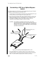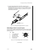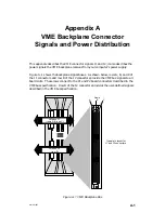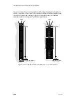
Connecting External Devices to VME Option Boards
4-36
014–001867
2–Slot
Deskside
Computer
(Rear Panel)
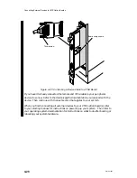
PHY B
TX
RX
PHY A
OP-
TI-
CAL
BY-
PASS
TX
RX
AViiON 5000 Series
Computers only
Rear Plug Panel
VFC EMI/Air Dam
Panel
(All Other AViiON
Computers)
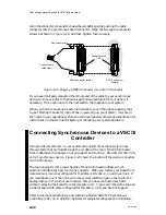
LED Lights
Connector for electrical cable
to optical bypass switch
ST connectors
for fiber optic
cables
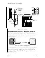
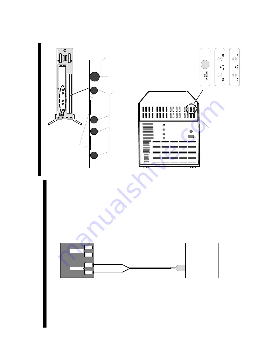
Figure 4–44 VFC Connectors
Single-Attachment Versus Dual-Attachment Connection
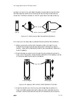
Your VFC board can have either a single-attachment or dual-attachment connection
to the FDDI ring. In a single-attachment scenario, your VFC board connects to a
concentrator, which in turn connects to the main FDDI ring. With this setup, you
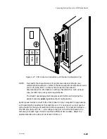
use only the PHY B (or Port B) of the VFC board. Figure 4–45 depicts a
single-attachment setup.
ÉÉÉÉÉÉ
ÉÉÉÉÉÉ
ÉÉÉÉÉÉ
ÉÉÉÉÉÉ
ÉÉÉÉÉÉ
ÉÉÉÉÉÉ
PHY A
PHY B
Tx
Rx
Tx
Rx
AViiON with VFC
Concentrator
ST–to–MIC Cable
Figure 4–45 Single-Attachment Connection
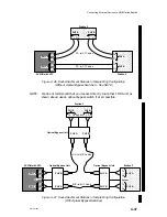
In a dual-attachment connection, the VFC board allows your AViiON computer to be
connected directly to the main FDDI ring network, either via the optical bypass
switch or a FDDI concentrator. An optical bypass switch allows you to take the
workstation off line, allowing the ring to bypass your station if the station has a
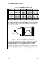
failure. Figures 4–46 and 4–47 show simple FDDI ring networks, without and with
optical bypass switches.
Summary of Contents for AViiON 5000 Series
Page 2: ......
Page 6: ......
Page 12: ...Preface x 014 001867 ...
Page 86: ...Configuring VME Option Boards 2 52 014 001867 ...
Page 144: ...Connecting External Devices to VME Option Boards 4 44 014 001867 ...
Page 150: ...VME Backplane Connector Signals and Power Distribution A 6 014 001867 ...
Page 196: ...Assigning VME Data Bus and Interrupt Priorities E 10 014 001867 ...
Page 206: ......
Page 210: ...Appendix Title ...

