Connecting External Devices to VME Option Boards
4-16
014–001867
Connecting a Parallel Printer to a Cluster Box
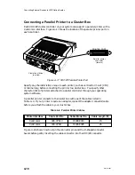
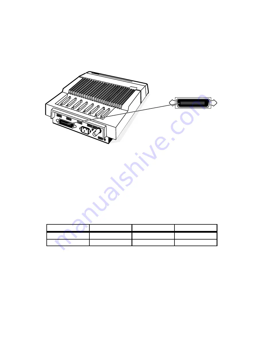
Each VDC/8P cluster controller on your system can support a parallel printer with a
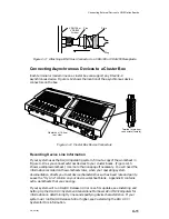
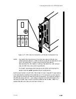
Centronics interface. Figure 4–17 shows the location of the parallel printer port on
each controller.
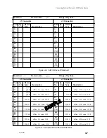
Cluster box (8-line)
rear view
PRINTER PORT
Parallel printer
connector
(female)
Figure 4–17 VDC/8P Parallel Printer Port
Specify any characteristics unique to each printer, such as vertical form unit (VFU)
or tab memory, before connecting the printer to a cluster box. You specify other
characteristics of printers attached to a cluster controller through your operating
system software.
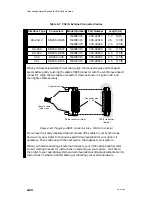
A parallel printer connects to the cluster box with one of the cables listed in
Table 4–4. If your printer requires an adapter, connect the adapter connector/cable
before you attach the cable to your cluster box.
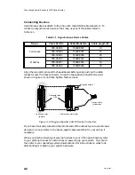
Table 4–4 Parallel Printer Cables
Printer Interface
Cable Part No.
Cable Model No.
Cable Length (ft)
Centronics
005–37910
15345E015
15
Centronics
005–37911
15345E025
25
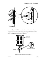
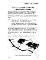
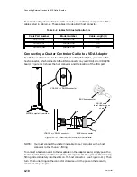
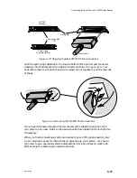
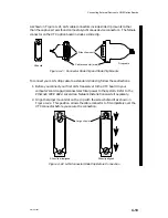
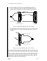
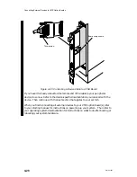
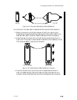
Figure 4–18 shows how to align the connector pins and the D-shaped connector
bevels before gently inserting the cable connector into the VDC/8P connector.
Summary of Contents for AViiON 5000 Series
Page 2: ......
Page 6: ......
Page 12: ...Preface x 014 001867 ...
Page 86: ...Configuring VME Option Boards 2 52 014 001867 ...
Page 144: ...Connecting External Devices to VME Option Boards 4 44 014 001867 ...
Page 150: ...VME Backplane Connector Signals and Power Distribution A 6 014 001867 ...
Page 196: ...Assigning VME Data Bus and Interrupt Priorities E 10 014 001867 ...
Page 206: ......
Page 210: ...Appendix Title ...


