Installing and Removing VME Option Boards
3-8
014–001867
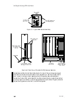
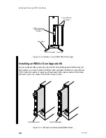
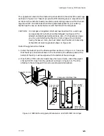
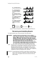
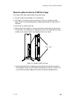
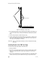
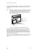
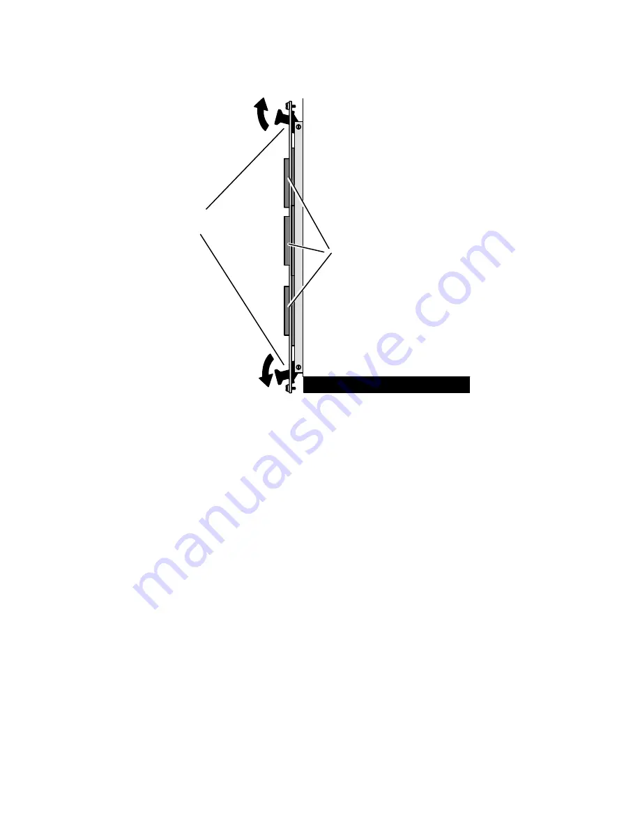
Board
ejectors
Device connectors
Computer chassis — side view
Figure 3–9 Releasing an Option Board
8. Pull the board straight out of the card cage, pulling gently by the handles. Do
not pull from side to side or otherwise risk bending or breaking the connector
pins.
9. Lay the removed board on a static-free mat or bag.
10. Install a replacement board as described in the next section, or install a cover
plate over the cage opening by inserting and tightening the securing screws.
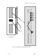
Use Figure 3–4 if necessary for reference.
CAUTION: Never run the computer without an air dam or cover plate over every
empty slot.
Installing Boards in the VME Card Cage
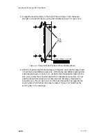
To install a VME option board, follow these instructions:
1. Set up an ESD kit.
2. Shut down your operating system; then turn off your computer system power.
Refer to your expanding and/or maintaining manual(s) for instructions, if
necessary.
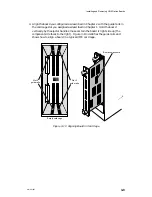
3. Remove the existing board or cover plate as described in the preceding section.
Make certain that you save the plate and screws; you may need them later.
Summary of Contents for AViiON 5000 Series
Page 2: ......
Page 6: ......
Page 12: ...Preface x 014 001867 ...
Page 86: ...Configuring VME Option Boards 2 52 014 001867 ...
Page 144: ...Connecting External Devices to VME Option Boards 4 44 014 001867 ...
Page 150: ...VME Backplane Connector Signals and Power Distribution A 6 014 001867 ...
Page 196: ...Assigning VME Data Bus and Interrupt Priorities E 10 014 001867 ...
Page 206: ......
Page 210: ...Appendix Title ...

