External Device Connector Pin Assignments
C-14
014–001867
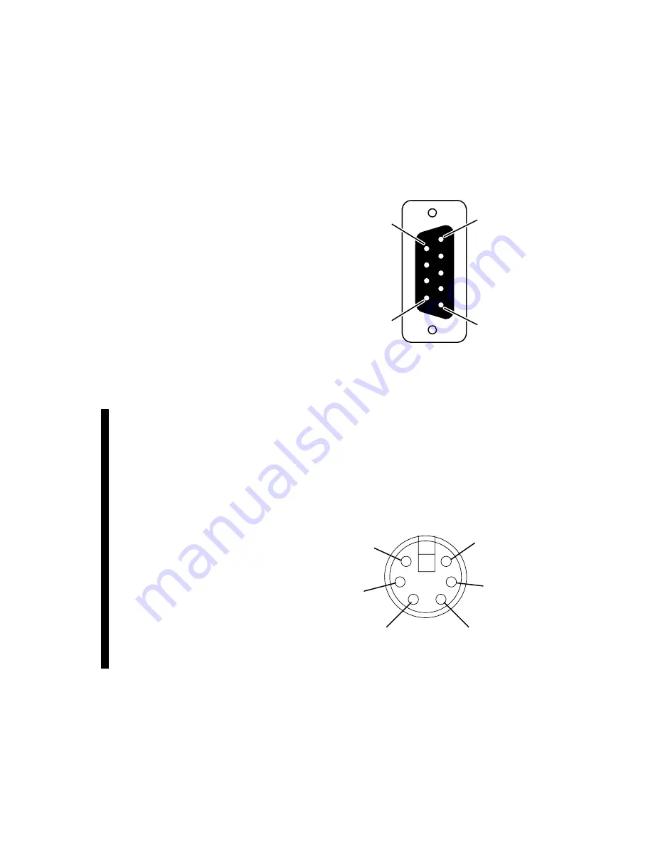
VTRC Interface Connector
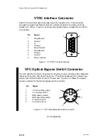
Each VTRC controller board includes a 9-pin D connector (J3.) This connector
provides the signal interface for direct or indirect connection to a network Trunk
Access Unit (TAU). Figure C–10 shows the signals and pin numbers for the VTRC
J3 connector.
1
6
5
9
Pin
Signal
1
Ring Receive
2
Ground
3
+5
4
Ground
5
Ring Transmit
6
Ring Receive
7
Ground
8
Ground
9
Ring Transmit
Figure C–10 VTRC Connector Signals
VFC Optical Bypass Switch Connector
The VFC board’s Tx and Rx connectors for Physical Units A and B are ST-compatible
jack-type connectors, and do not have pins. The optical bypass switch, however, has
a 6-pin mini-DIN connector at the VFC board end. Figure C–11 shows the signals
and pin numbers for the optical bypass switch connector.
Pin
Signal
1
+5 V secondary switch
2
+5 V primary switch
3
GND primary switch
4
GND secondary switch
5
Common to pin 6
6
Common to pin 5
1
2
3
4
5
6
Figure C–11 VFC Optical Bypass Switch Connector
End of Appendix
Summary of Contents for AViiON 5000 Series
Page 2: ......
Page 6: ......
Page 12: ...Preface x 014 001867 ...
Page 86: ...Configuring VME Option Boards 2 52 014 001867 ...
Page 144: ...Connecting External Devices to VME Option Boards 4 44 014 001867 ...
Page 150: ...VME Backplane Connector Signals and Power Distribution A 6 014 001867 ...
Page 196: ...Assigning VME Data Bus and Interrupt Priorities E 10 014 001867 ...
Page 206: ......
Page 210: ...Appendix Title ...

