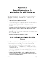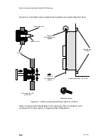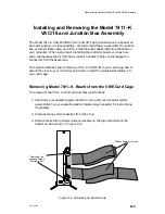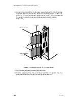
External Device Connector Pin Assignments
C-4
014–001867
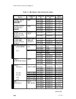
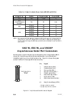
Table C–2 Cluster Controller Power Cords (VDC/8P and VDC/16)
Voltage (V ac)
Part No.
Frequency (Hz)
Power Suffix
100
NA
50/60
–1
120
(North American
standard)
NA
60
none
40
109–813
50
–5
240
109–809
50
–6
0
109–812
50
–7
0
109–811
50
–8
220
109–815
50
–9
109–810
50
–0
NOTE: Each cluster controller package includes a 100/120 volt power cord, shipped with the
controller box. If your site requires 220 or 240 volts ac, make sure you received the
correct number and type of additional power cords; do not attempt to use the 100/120
volt ac cords.
VAC/16, VDC/16, and VDC/8P
Asynchronous Serial Port Connectors
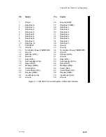
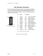
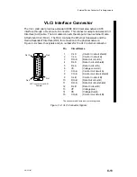
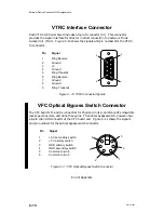
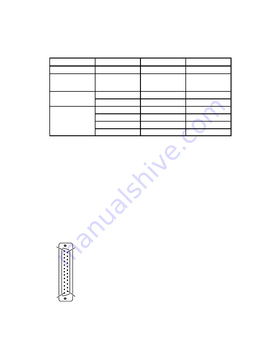
Serial devices connect to the serial ports through RS–232–C 25-pin female DB25
connectors. Asynchronous connectors are located either on a VDA/128 (and
VDA/255) cluster box or on a VAC/16 junction box. Figure C–1 shows the signals
and pin numbers for these asynchronous connectors.
Asynchronous device
connector
(female)
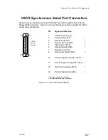
Pin Signal
1
Chassis Ground (CG)
2
Transmit Data (TxD) <
3
Receive Data (RD) >
4
Request to Send (RTS) <
5
Clear to Send (CTS) >
6
Data Set Ready (DSR) >
7
Signal Ground (SG)
8
Data Carrier Detect (DCD) >
20
Data Terminal Ready (DTR) <
< indicates received by controller
> indicates transmitted from controller
1
13
25
14
Figure C–1 Asynchronous Serial Connector Signals
Summary of Contents for AViiON 5000 Series
Page 2: ......
Page 6: ......
Page 12: ...Preface x 014 001867 ...
Page 86: ...Configuring VME Option Boards 2 52 014 001867 ...
Page 144: ...Connecting External Devices to VME Option Boards 4 44 014 001867 ...
Page 150: ...VME Backplane Connector Signals and Power Distribution A 6 014 001867 ...
Page 196: ...Assigning VME Data Bus and Interrupt Priorities E 10 014 001867 ...
Page 206: ......
Page 210: ...Appendix Title ...

