Special Instructions for Model-Specific VME Hardware
D-3
014–001867
Installing and Removing the Model 7411–K
VAC/16 and Junction Box Assembly
The Model 7411–K VAC/16 differs from most VME option boards due to a special air
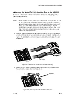
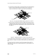
dam and junction, or J-box assembly. We recommend that you assemble the junction
box, external ribbon cable, and 7411–K VAC/16 board before installing the board in
your computer. When removing or installing the controller board, you must use
extra care because the air dam has no ejector handles to help you disengage the
connectors from the backplane.
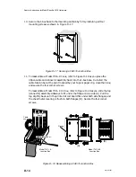
This section describes how to remove a 7411–K VAC/16 from your card cage, how to
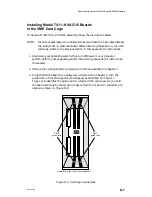
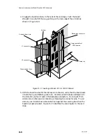
attach the J-box to your controller, and how to install the completed assembly into
your card cage.
Removing Model 7411–K Boards from the VME Card Cage
To remove a Model 7411–K VAC/16, follow these instructions:
1. Shut down your operating system before turning off your computer system
power. Refer to your expanding and/or maintaining manual(s) for instructions,
if necessary.
2. Disconnect any external devices from the J-box.
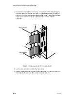
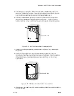
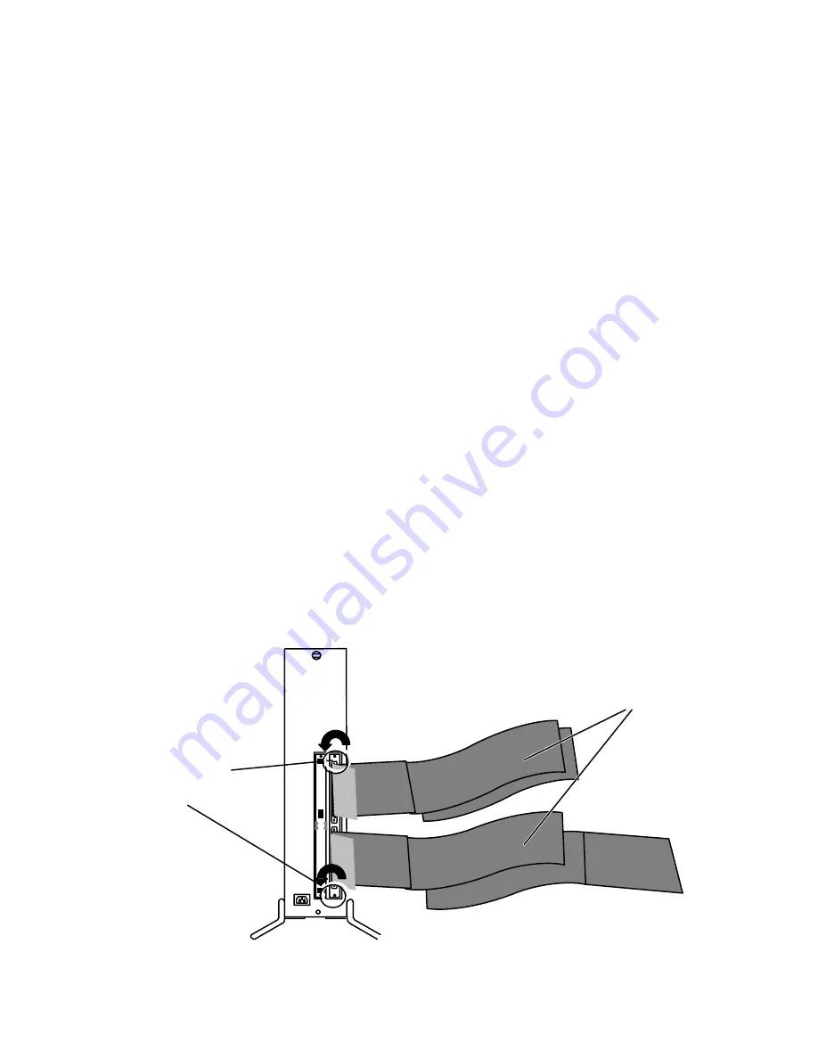
3. Remove the securing screws and any washers on the top and bottom of the
board’s air dam, shown in Figure D–2.
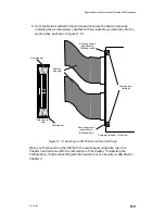
Removing the
securing screws
(Phillips or flat)
Ribbon cable(s) to J-box
Figure D–2 Releasing Air Dam Screws
Summary of Contents for AViiON 5000 Series
Page 2: ......
Page 6: ......
Page 12: ...Preface x 014 001867 ...
Page 86: ...Configuring VME Option Boards 2 52 014 001867 ...
Page 144: ...Connecting External Devices to VME Option Boards 4 44 014 001867 ...
Page 150: ...VME Backplane Connector Signals and Power Distribution A 6 014 001867 ...
Page 196: ...Assigning VME Data Bus and Interrupt Priorities E 10 014 001867 ...
Page 206: ......
Page 210: ...Appendix Title ...

